Search the Community
Showing results for tags 'm17x'.
-
Hi guys, I apologise in advance if this was asked before, Basically I have acquired an AW m17x r4 with a faulty graphics card. The card was the 675m. I just happen to have a GTX 980m out of a faulty MSI GT60. I did a fresh install of Windows 10 on the machine in UEFI mode with secure boot enabled however the card just shows up as Microsoft Basic Display Adopter and Nvidia Driver installer says there is no compatible hardware. Is there a way to make this card work? Something like a modified driver or perhaps a vBIOS flash? Any help would be greatly appreciated, thanks guys! Update: Trying to flash a clevo vbios, but get board ID mismatch in nvflash Board id E90C vBIOS id E906 Could someone direct towards a compatible BIOS for this card? Thanks!
-
I have installed a 980m card in an M17x from early 2014 and am now here to ask the experts of this fine establishment if they can help with what needs to be done to get it to work, if at all possible. It tries to upgrade a shorted out 780m. Modded driver was installed (445.75 WHQL from 2020.3.23), but device manager says error 43. sBIOS is stock A17 from Dell. UEFI enabled, legacy and safe boot disabled. OS is Windows 10 Home 64-bit on an SSD. Can it be done at all? If it can, what needs be done? Edit: I think my model is actually 17 R1, judging by the date, processor being a 4th gen i7 (4700MQ) and also this matches my regulatory model. I know this is my only post here and in I come, asking for help, but... pretty please help? Further edit: I have identified the 980m as being a Dell version. (as per GPU-Z)
-
Hey all, just got my m17xr4 and put my 980m from my m15x (old) in it. I was able to score much higher graphics score in firestrike even though it is a much older machine. I made a custom vbios for the m15x to get rid of any throttling, and am in the process of making on for the m17xr4 but I'm wondering if there is anything else I have missed to deal with the throttling. any help would be appreciated
-
Hello Techies! New to the forums and I own a Alienware M17X R3 that has never had anything done to it and finally after 9 years the HDD crapped out, i purchased a Samsung SSD that I will be receiving next thursday so just getting a low down on what the proper procedure is. I currently have Bios A03 which will not give me SATA III speeds either from what I have read and will need A08? Will the Dell Bios update work for me or should i be trying to go with A12 unlocked? Can i do the update off windows as soon as do a fresh install on the new SSD? Or do I have to make a bootable usb? Sorry im not dumb with computers but not as smart as I want to be haha Thanks in advance for every ones help! I also want to upgrade my GPU at some point which current is an Nvidia 460M, what is the best/cost effective upgrade I should do and do I have to have a certain Bios to run that as well?
-
 Hello Fellow Tech Gurus!I am having a huge headache after upgrading the ram memory of my m17x r3. First let me start by saying I have been experiencing issues with my current ram setup recently, and so i decided to replace the ram inside of my computer, thinking they had gone out on me. It originally came with x4 2gb memory sticks, and as I started to experience issue, I started to removed them, and I was down to 1 2gb stick. It seems to me ram slots 1 & 2 are not working properly as when I put ram memory into them I would get BSOD in 5-10 mins of computer usage after boot. So I am thinking the slots have gone out. I also tested each slot individually and still same effect.So I went on the try out slots 3 & 4 under the keyboard, which seems to work just fine when I use only 1 ram chip in one or the other. But the problem occurs when I try and fill both ram slots in slots 3 & 4 under the keyboard with crucial 2x 8 gb of ram sticks, which total to 16gb total ram memory.BSOD and freezing occurs like crazy. But if I use just one of the ram sticks in either slot, no problem.I dunno if this is hardware or software. I am think that my motherboard is on its way out the door, but any suggestions you all have would be great. I have already clean installed win 7, and is currently running bios A10 (unlocked, I believe)I would also like to note that my motherboards internal vga is not detected, and just noticed this a few days ago upon trying to figure out the ram situation.other issues is my laptop battery is pretty much dead, and the only for my computer to cut on is if the AC adapter is connectedI would also like to know can 1x 16gb 1600 ram stick run in my computer? or is it not supported by my motherboard? thanks!Specs:Alienware M17xR3 (2011 3D FHD ed) Service Tag: 30W75Q1 Bios ver:A10 (should be unlocked) Operating SystemMicrosoft Windows 7 Home Premium (64-bit) ProcessorIntel® Core™ i7-2960XM CPU @ 2.70GHz ChipsetIntel® 6 Series/C200 Series Chipset Family GraphicsNvidia GTX 680m AudioIDT High Definition Audio CODEC High Definition Audio Device Networking and I/ODW1501 Wireless-N WLAN Half-Mini Card Atheros AR8151 PCI-E Gigabit Ethernet Controller (NDIS 6.20) HMA TAP-Windows Adapter V9 MemoryCrucial 8 GB (x2 qty) DDR3 PC3-12800 • CL=11 • Unbuffered • NON-ECC • DDR3-1600 • 1.35V • 1024Meg x 64 • (these only work under bay 3 or 4, but not dual 8gb at the same time, otherwise BSOD) Configuration ID: CT3283724 StorageWDC WDBNCE5000PNC SSD (installed into bay 0)
 -

[GUIDE] Dell 330W Power Adapter Mod for the M17X
Nospheratu posted a topic in Alienware M17x / AW 17
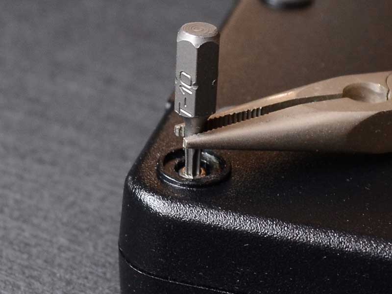
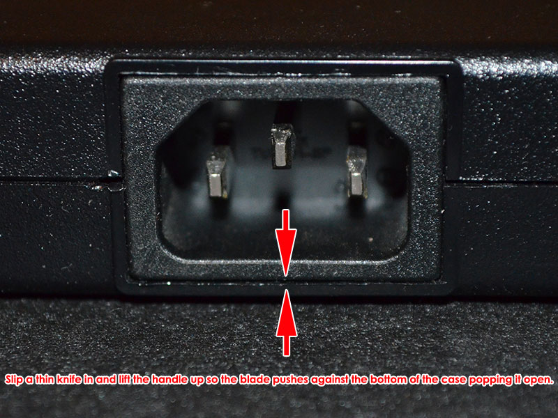
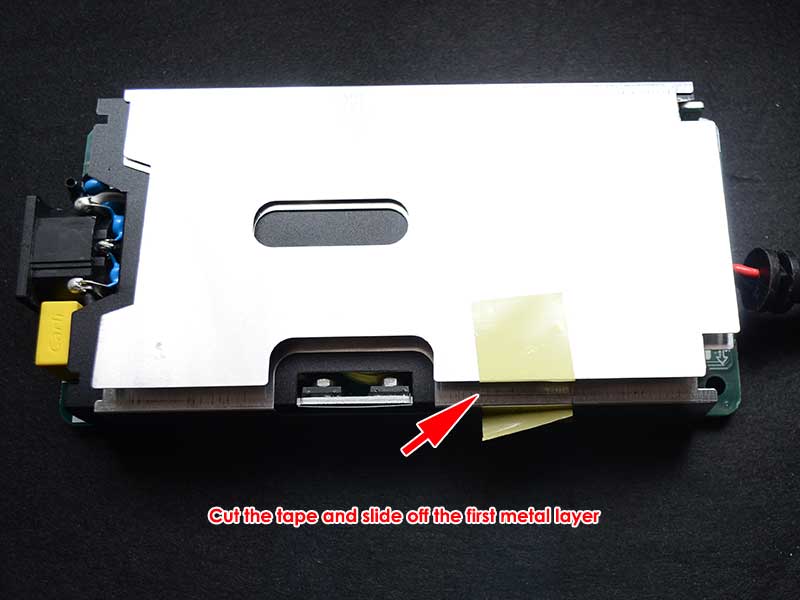
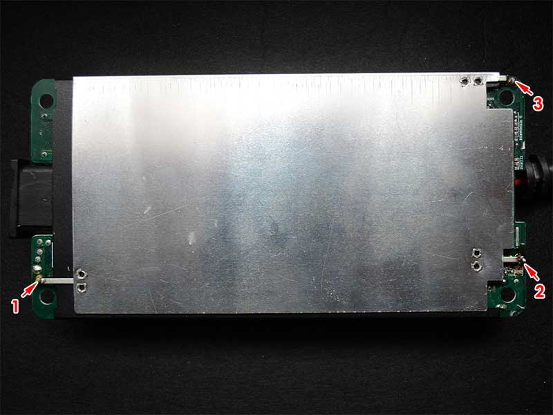
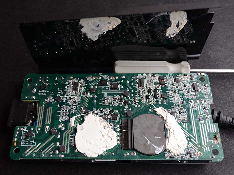
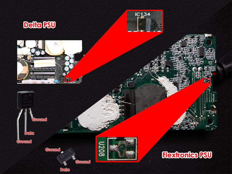
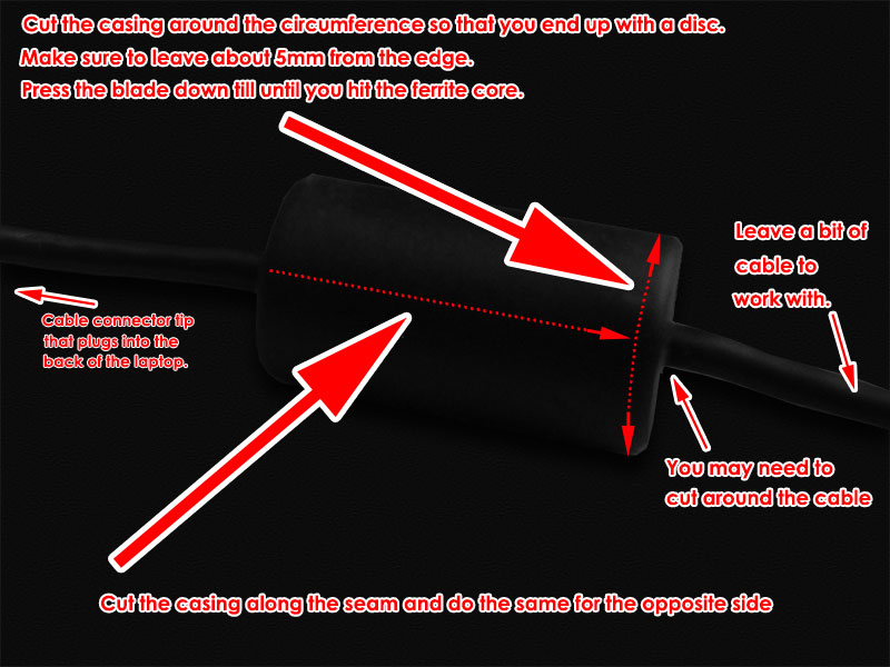
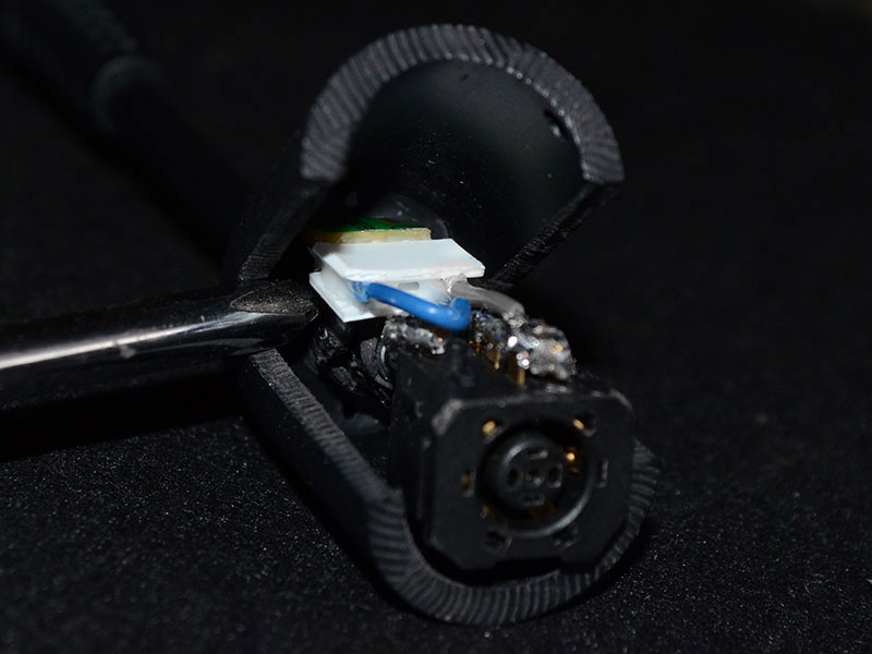
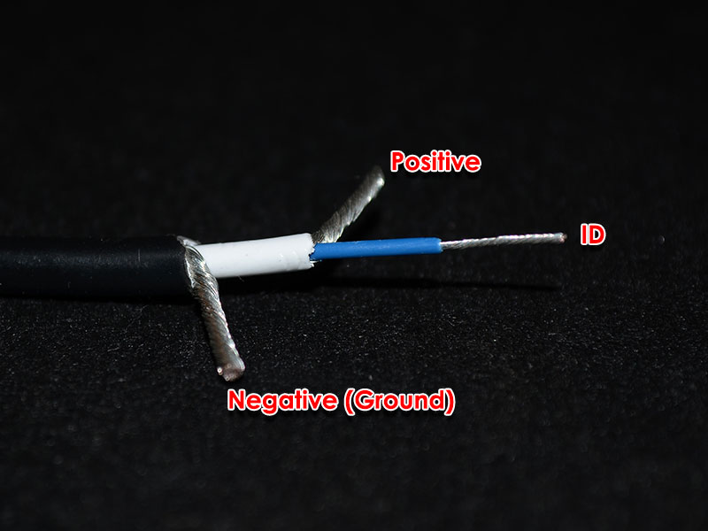
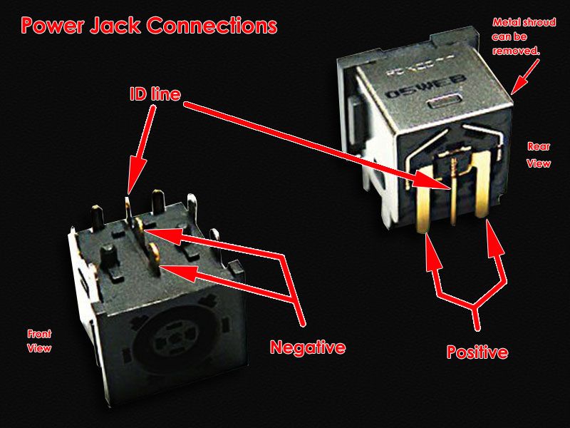
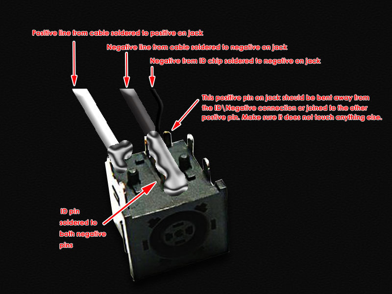
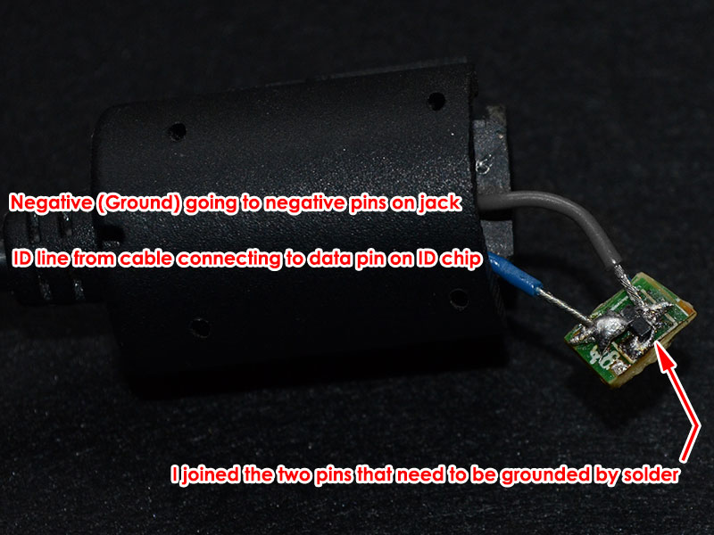
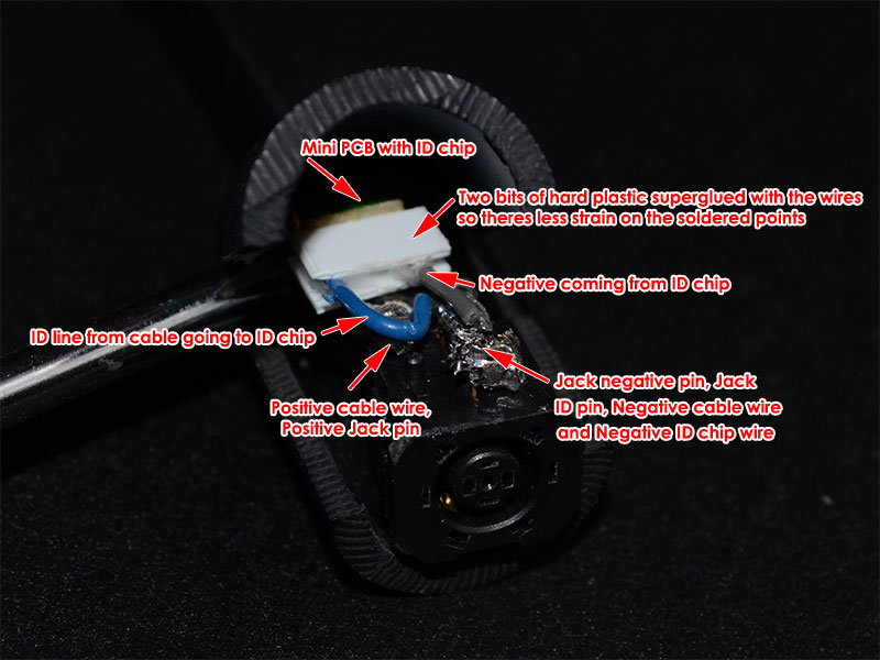
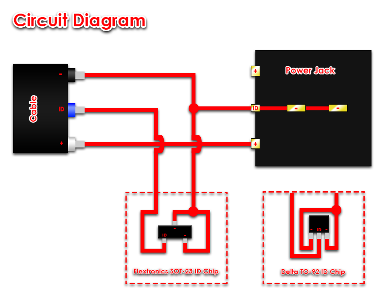
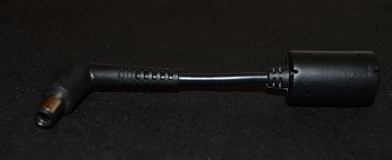
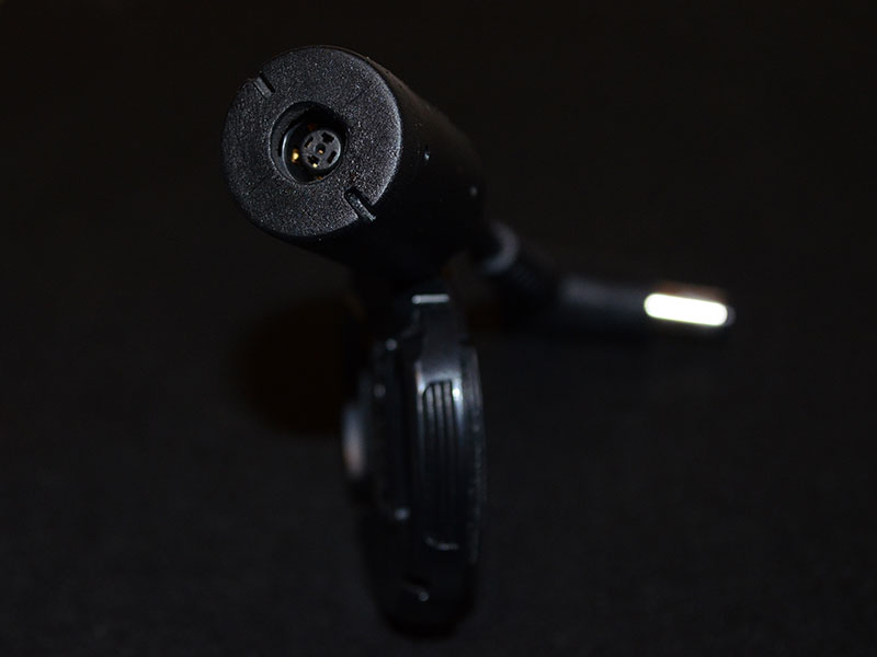
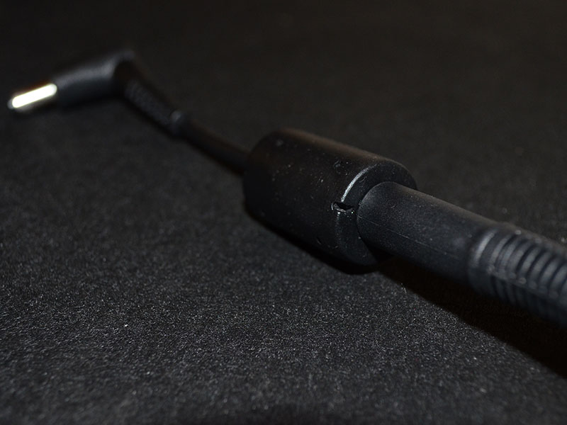
This modification involves going a step further than a straight ID chip swap between the 240W and the 330W. The reason I chose this method was, I did not want to perform the mod again in the rare case that the 330W died and I had to get a new one. In order to complete this mod, you will require the following items. 1. Dell 330W PSU (This PSU was built for the M18X and X51 product lines). Part Numbers: Y90RR / 5X3NX / F0K0N / XM3C3 / 331-2429 2. Dell 240W PSU (Either a Flextronix or Delta). Part numbers: PA-9E / J938H / Y044M / U896K / J211H / Y044M 3. Dell or HP standalone PSU cable/Connector. I used a right angle connector but any Dell/HP 7.4 x 5.0mm barrel connector will work. 4. M17x/M18X Power Jack. The part number for this power jack seems to be P01E. Look for the one that resembles the one used here. 5. Small PCB designed for a SOT-23 packaged chip. (If using the Flextronics 240W PSU). 6. Small housing (Optional depending on whether you would like to mod the ferrite choke housing) PSU DISASSEMBLY First we begin with the disassembly of the 240W PSU to retrieve the ID chip for our adapter. Since I had the Flextronics version some of these steps might not be the same for the Delta PSU. We start by lifting up the rubber feet on the bottom of the 240W using your nail or a flat tool. Underneath each rubber foot you will find a screw which you can go ahead and unscrew. One of the screws will be a tamper-resistant Torx T10 type, the difference to a normal Torx T10 being a small pin the centre so you would have to use a Torx screwdriver with a hole in the center. TIP: If you do not have this tamper-resistant screwdriver you can use a normal Torx T10 screwdriver but you will have to hammer down the pin at the centre of the screw slightly in order to get the normal T10 screwdriver to grip. Once you have removed all screws you will have to pry open the casing. I stuck a thin knife between the power plug and the casing to gently pry it open. The top half and bottom half of the casing are held together by interlocking clips. Twist the case a bit to get them to unclip. Then remove the PSU from the case. You will then be presented with the first metal layer which is held on by tape. Cut the tape and slide out the first metal layer. You will then see the second metal layer which is held in place by 3 points soldered onto the PSU PCB. It is indicated in the picture below. Desolder all 3 points and remove the second metal layer. The last layer is black and seems to be a type of flexible hard plastic. It will be stuck in place by white thermal stuff on the PCB, simply lift it and peel it away. Depending on whether you have a Flextronics or Delta PSU your ID chip will look different. Desolder this chip and keep it in a safe place (If you lose it, you have to buy a new 240W PSU). On the Flextronix PSU the chip is also stuck in place apart from being soldered on, so you have to work quickly heating the solder and pushing the chip away with a bit of force. To reassemble the PSU reverse the above steps. You can still use this PSU connected to the adapter with your M17X so it won't be collecting dust. THE ADAPTER MOD You will have to decide on whether you want to mod the ferrite choke housing into your enclosure or use a dedicated enclosure (small as possible as this circuit is tiny). If you are using a dedicated enclosure jump straight to the labelled wire photo to continue. If you would like to mod the ferrite choke housing continue reading. I did not take sufficient pictures during this portion as I was unsure if the ferrite choke housing would work. The rubber around the ferrite choke and the connector that I purchased was soft and very flexible which made it easy to work with. I used a knife and pressed against the rubber of the ferrite choke housing for a clean cut so that I could glue it back together. I cut off one end and then length ways along either seam of the housing making sure to leave a bit of extra cable. Here is a picture of what we’re trying to achieve with the cutting. You will then see the ferrite choke which you can crack with a hammer. Remove the pieces (be careful as they will be very sharp). Then the cut off the cable strain relief that's covering the cable with small wire snips. You will then see the cable which you can strip to positive, negative and the ID line. You will then need to connect those wires to the power jack. The two pins at the top are negative. The two pins at the back forming the shape of a U are positive and the pin at the back in the centre is the ID line. Solder the positive wire to positive pin and negative wire to negative pins as shown in the image below. The negative wire can be soldered to the negative pins and simultaneously joining the ID pin on the jack. The reason behind joining the ID pin to the negative pins on the jack is because we need to ground the ID line coming from the 330W in order for it to operate beyond its artificial 240W limit. Now all that’s left to do is connect the ID chip. If you have the Flextronics PSU the ID chip will be in a SOT-23 package and the Delta ID chip will be in a TO-92 package. The Flextronics SOT-23 package is difficult to work with and should be first soldered to a bit of PCB that had a SOT-23 package so that you do not break the legs off. I initially soldered the wires directly to the legs and moving it about in my "enclosure" to find the best spot to place it was too much stress on the chips tiny legs and they broke off... yes, all of them. Luckily I could still see a tiny bit of metal from each of the legs. I managed to salvage it by soldering it to a piece of PCB that I jacked from a broken mouse which had SOT-23 connections. The blue ID wire coming from the cable needs to be soldered to the data leg of the ID chip. Connect the remaining two pins from the ID Chip together and then to the negative connection on the PSU jack. Dont judge my pathetic soldering skills! Place your ID chip into the enclosure and test the adapter to make sure all your connections have proper contact. If it’s working properly you can close it up. I considered flooding the enclosure with silicone to secure the ID chip and its connections but I did not, as I thought it would be more work if one of the connections broke and I had to open it up again. You can do it if you like. I used a drill to make the hole at the centre of the disc large enough for the 330W connector tip fit through. I then stuck the enclosure back together using superglue along the sides and then attaching the disc. Add a bit of glue to the disc/jack so that the disc and jack are stuck together as well. This is so that the jack does not move when plugging the PSU connector tip in. THE COMPLETED MOD Pros/Cons over the ID Chip swap Mod Pros - Allows you to use any PSU irrespective of wattage as long as the connector tip is compatible with the power jack. - If the 330W PSU dies all you have to do is plug a new one in. No need to perform the mod on a new 330W. - No need to open up the 330W at all. - Your ID chip donor 240W PSU can still be used with your M17X by attaching this adapter. Cons - Allows you to use any PSU irrespective of wattage as long as the connector tip is compatible with the power jack (Could be dangerous with low wattage PSU's). - A lot more work compared to swapping the chips. Notes: I also had to trim a bit of rubber at the right angle connector for the cable I used as it’s a bit of a tight fit if you don't. The rubber around the connector did get a warm at the right angle after testing but it's being blasted by the heat of the CPU fan continuously so I don't think it’s the connector itself that's causing it. These cables are very short and should be able to handle the power easily. Since there are two positive terminals you will have to either split the positive wire coming from the PSU connector to each pin or join both pins (bend one pin over to the other and solder them together making sure to place an insulator to cover the ID pin) and solder the positive wire to a single point. Also worth noting is that this adapter mimics the original 240W adapter perfectly. So if you experienced the "plugged in, not charging" issue when connected this adapter will not resolve it (I still have to pop the battery and clip it back in to resolve). Credits: @imsolidstate, without his in-depth investigation this would have not been possible. His website detailing his investigation and the ID chip transplant can be found here and the subsequent update here. DISCLAIMER: Perform this modification at your own risk. I take no responsibility for any damage caused by technical error, user inexperience or stupidity.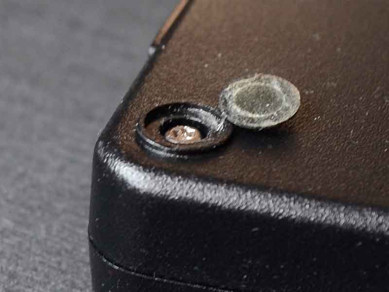


- 69 replies
-
- 15
-

-
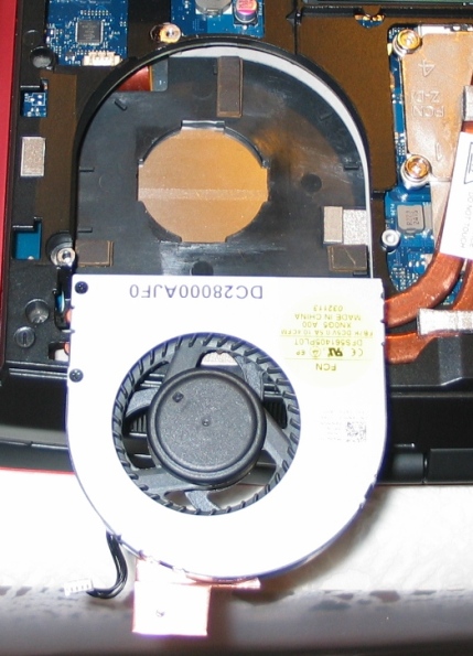
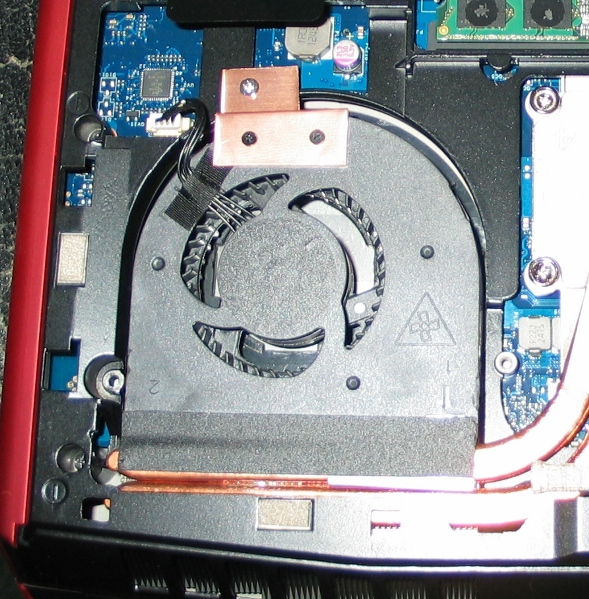
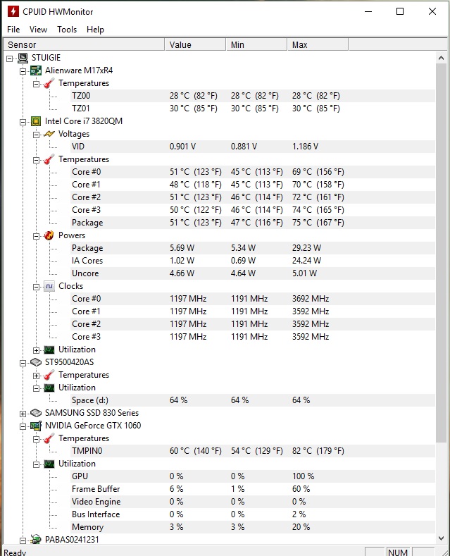
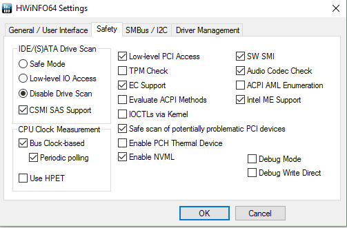
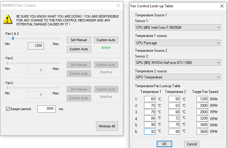
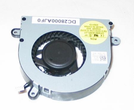
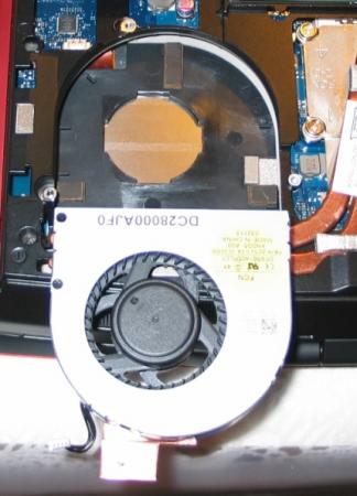
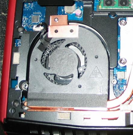
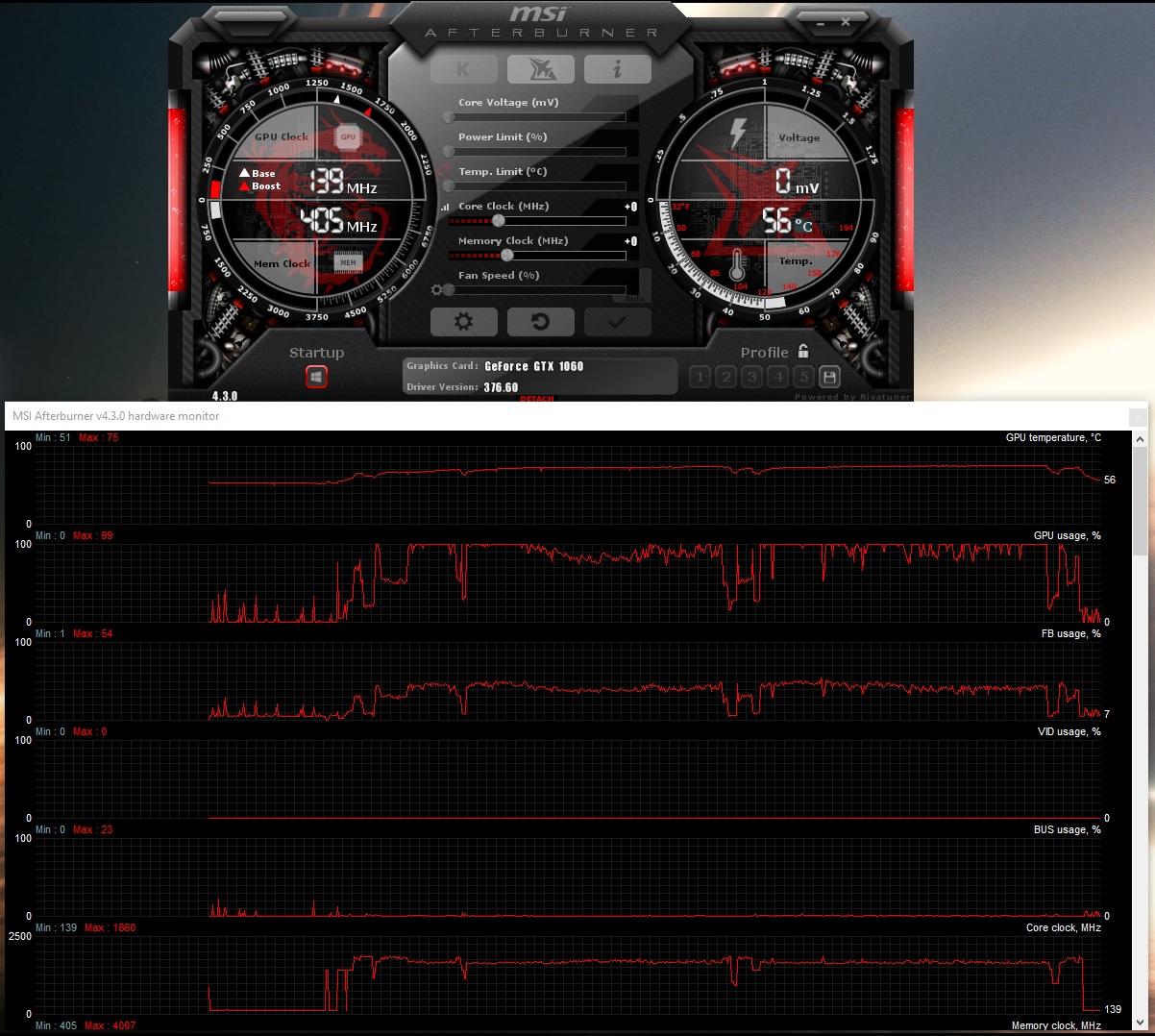
Hi all, This is just to report the success of installing a gtx 1060 on my M17X R4. Mine is the 3D version and as far as I'm aware, you need a screen in eDP mode (120Hz 3D model) for it to work (confirmed) on top of UEFI support to boot up. See here for the gtx 980m install which is the same for this card, but the 980m works on 2D models too: https://www.techinferno.com/index.php?/forums/topic/8103-installed-980m-in-m17x-r4120hz-3d/ HDMI in and out works but it does raise the question if the gtx 1060 will work on the 2D model via HDMI out. It should do as it's the eDP connector for the laptop screen is the issue here. Also 3D mode will no longer work (like anyone cares about 3D anymore ). The cards above the 8xxm series have no 3D support. Prerequisites A 120Hz screen is needed to pascal GPUS as only the 120hz connector in the laptop supports eDP mode. Keep your current card, in case you try modding your Bios or something like that, if settings become reset, UEFI is usually off by default. That means in this situation the GTX 1060 won't work without changing the Bios settings. Install your old card as it supports non-UEFI and UEFI modes. UEFI mode: This is must for the reason above. Windows needs to be installed on a GPT partition to use this feature. As this laptop origianlly came with windows 7, GPT and UEFI originally was not used. However Bios updates and windows 8+ could use it so UEFI was enabled. Install a fresh copy of windows on a GPT partition. The windows installation menu can help you with that. https://technet.microsoft.com/en-gb/library/dn336946.aspx Bios settings: In the boot options, set to UEFI mode, disable fastboot and legacy options. This ensures that your old card and the Pascal card both work when you swap them out. Installation It seems the laptop just about supports it. One Major thing to be aware of is the installation. For at least the MSI model of the GTX 1060, you need to use very thin heat pads as the core only just makes contact with the heat sink otherwise. I have found that on the core side are some new resistor blocks (Labelled R.22) that weren't in my old GTX 680m and thankfully they are the exact height of the core, so it isn't impossible to mount the heat sink. It's a very fine mark but provided you use thin pads (stock GTX 6xxm cards have nice thin ones) and a tightly screwed X bracket, you can get good cooling performance. The top R.22 blocks also do not need thermal pads (may benefit from thermal paste though) as you need as little height as possible. I'm aware of two types of heatsink used in the m17x r4. Both will work but there is a protrusion (in red) that can prevent proper contact with the core. If on a copper cornered heatsink (second image), you may not have to file this bit down. If you seriously have no tools to do this, you can very carefully bend this section VERY slightly to provide a little more clearance. To ensure good contact with other components in this case, use thicker pads or more paste on this section. (Top) Taken by Zoldago (Bottom) Taken by Decool Drivers Drivers are fine, just go to laptopvideo2go and get the latest drivers with the modded .inf files. Remember to use DDU before installing . Simple guide for drivers:) - uninstall any graphics drivers, including ones automatically downloaded by windows (disable windows update if need be). Using DDU ensure every trace is wiped clean to avoid any problems - Disable driver signature enforcement (Shift + restart button in the start menu -> troubleshoot -> Advanced options -> Startup settings) OR f8 at boot screen (windows 7) - Run official installer, quit once the driver files are extracted. - Place the modded .inf file into "display.driver" of the extracted files - run "setup.exe" from extracted folder. Done! Bios + screen Generally, a modded bios is not needed as all necessary options are already available. Some scenarios may need a display type change or the iGPU cannot be disabled the usual way. To convert from a 60hz to a 120hz screen, you need to ensure that when booting up on the 60hz screen to disable the iGPU (FN+ F7) (Check BIOS settings to ensure it stays off). Once in dGpu only mode, you can go ahead and install the 120hz screen. 120hz screens do not support optimus as the iGPU is incompatible. Performance wise it's pretty close to a desktop 1060, hitting a score of ~3600 in time spy and ~12,000 graphics score in Firestrike (desktop scored ~14,000). Temps settle at 75C as the card is limited to ~80W (so very limited OC for now ). First Screenshot below used the stock paste that came with the card. Highly recommend a different paste such as mx-4 paste which I used (second screenshot). I doubt it will work on a M17X r3 due to the lack of UEFI support. Fan control and monitoring I use MSI afterburner for monitoring temps. You can also use HWinfo to control the fans, seeing as the 1060 is an 80W GPU compared to the 100W that the laptop is capable of cooling. If you're interested in lowering the fan speed for the sake of noise, use HWinfo. I'm aware that a system lock up can occur when using the fan control feature. However, so far I may have a solution. - Remove the main battery. A fix for many users and easy to implement - Alternatively use the settings provided in my screenshot. I know that the ACPI features are likely to be the main cause of lockups, but to be sure copy my settings and only monitor the sensors needed for fan control (e.g. CPU package temp and GPU temp). the author of this program is aware that the battery monitoring is the cause for lock ups (which uses the ACPI in windows) Remember that you can only control both fans at the same time! Be sure to stress your CPU with a program prime95 to ensure your CPU does not overheat with your new fan settings. Also use both fan tables, one for the CPU and the other for the GPU so the fans spin up under loads from either. A final note. I would set a re-spin period on the fan control menu to reduce fan pulse. I found 2-3 seconds ideal. In my machine at least, the BIOS sets the fan speeds higher than needed before settling down to their target speed. E.g. at 4000 rpm, the fans spin up to 4600 rpm and in around 10 seconds slow down to 4000. Below is my preferences, although you may not want to run components quite as hot. Under max load, the CPU hits 90c and GPU 78c. Good luck and enjoy!

-
Hi, I bought a alienware m17x r4 a few weeks ago. The problem is: I have noise (distorsion) on the right speaker. Had anybody in past the same problem and is it a known problem regarding this model? I feared at the beginning that the soundblaster is defect but I tested it with headphones and everything is fine. I already ordered a new speaker pair and will install it within the next weeks. But if you tell me that this problem is known and not resolvable I can save my effort.
-
Hi, I read a lot of different threads about the maximum possible M17X R2 configuration. But after I was more and more irritated. What is at the end the best performant GPU solution (with unlocked bios and dirver mod) but WITHOUT manual fan control and such things. Because if I want to sell one day my M17X R2 I don't want to explain and force the buyer to control the GPU fan per hand.
-
I got a single pcs of latest Pascal architecture Quadro P5000 based on GTX1070 Main difference is It has 16GB of VRAM. As you can see, It is MXM3.0 B type board few more detail pictures for P5000Compare with My GTX980MSize is same and has similar layouts too.Fit perfects with my M17X R4I did upgrade my Heatsink with 3rows for CPU and 6rows for GPU for keep it cool.Here is What Bios shows up.I got Win10 64bit with EFI boots.I tried with Single PEG but failed.Seems Pascal only support eDP signal for screen.I guess If I change to 3D screen, might works for Single PEG use. Update me If anybody has tips for this. Here is How it shows out in Windows 10As there is no official driver for P5000 for laptop's yet, most of information not shows out correct specs.But as you cans see it has 16GB VRAM and 2048 shader units.This is 3DMark Fire strikes for P5000check for more details with this links : http://www.3dmark.com/fs/11422803 I did some of tests and decide to wait official driver come out from vendor's or nVIDIA. It's not working 100% performance yet, but still can feel how powerful Graphics card it is.
-
Hey whats up guys and gals? New member but have been researching here for quite some time. I have a... 2011 Alienware M17x R3 i7-2630QM CPU 16GB RAM Nvidia GTX 460M GPU Windows 8.1 Pro x64 I happened to find a good deal on ebay after a heated bidding war lol. So basically I want to upgrade the GPU to get a liitle more performance out of her. A few games have some terrible lag as Im playing. Ive been looking on ebay and doing research on a new one for the past couple weeks. Should I go with a 580m or save the extra money and get a 680m or a 780m? Something along that line. I dont wanna spend too much on a newer GPU. Any opinions would be appreciated!
-
Just recently puchased a Clevo Gtx 780m on ebay and inserted it into my Alienware m17x r4. I'm terrible dissapointed to find the BIOS a12 unlocked and device mananger doesn't detect it at all. Are there some steps I have to undergo to make it work?
-
Just recently puchased a Clevo Gtx 780m on ebay and inserted it into my Alienware m17x r4. I'm terrible dissapointed to find the BIOS a12 unlocked and device mananger doesn't detect it at all. Are there some steps I have to undergo to make it work?
-
CPU Fan Upgrade Procedure for M17x R3/R4 (2.0CFM->10.4CFM!)<o:p></o:p> My original CPU fan was adequate (not great but adequate) fora 3740qm CPU @ 3.7GHz but when I upgraded to a 3920xm CPU and overclocked to4.1GHz x 4 cores, I needed more cooling - a lot more. Running a 60-second CPU stress test on all four cores in Intel XTU, with a 65watt CPU TDP programmed, and a core voltage of 1.351v, the difference is asfollows: · With original fan, system runs @ 4.1GHz for ~28 seconds before dropping to3.5-3.7GHz because of heat. On longerstress tests, it DOES NOT recover from this reduced speed state becausecooling is not adequate. Core Max: 92-95Celsius. · With this fan mod, system runs @ 4.1GHz for ~55 seconds before dropping to 3.7GHzbecause of heat. On longer stress tests,it DOES recover from this reducedspeed state and spikes of ~4GHz are seen for the remaining duration of thetest. Core Max: 92 Celsius every time. <o:p> </o:p> So here are the stepswith some pictures: 1. Procure an M14x R2 fan. It MUST be an R2 fan!! The fan blade design is clearly different so usemy picture as a reference. There are many eBay sellers, for example, selling the R1 fan as an "M14x series fan," implying that bothrevisions use the same fan - which is not true. The R1's fan has a 2CFM sticker rating while the R2's has 10.4! The markings to search for are: XN0G5 and/or DC28000AJF0. I got mine here: http://www.aliexpress.com/store/product/Cooling-Fan-for-Dell-Alienware-M14x-XN0G5/207462_647373968.html Note: Do not just swap the M14x's fan blade into your existing M17x fanshroud. I tried that first and it doesnot increase airflow. You need the newblade AND the new shroud for this to be effective. 2. Remove your original CPU fan. There are three screws that hold it in. Also disconnect its power jack from themotherboard. While you have access, youmight want to blast that exposed exhaust port with some compressed air to makesure everything is clean. 3. Notice the three mounting brackets that protrudefrom the sides of the fan shroud in the picture from Step 1. You'll need to cut them off so the shroudwill fit. I used a Dremel with agrinding wheel. There's also one smallblack screw in the corner with the yellow sticker. You'll need to remove it and grind down thatprotrusion as well. Save that screw forlater btw. 4. Make spacers/pads to hold the new fan up. The factory pieces will not line up so you'llwant something under the fan for clearance and to allow air intake from theunderside. I used small pieces of arubber material called Dynamat but padded mirror tape would work, as would manylayers of electrical tape placed on top of each other. It doesn't matter what you use - as long asit won't melt - and you'll want it to have a small footprint so it doesn'tblock airflow. I made my pads abouttwice the height of the factory material. Higher pads will allow for greater clearance and more air intake - justbe sure the fan still lines up with the heatsink and the case closes over it. This picture shows the three pads I made, and the fan shroud with its originalmounts ground off. 5. Create a mounting bracket to secure the fanshroud at the point farthest from the exhaust port. You could optionally fabricate mounts to lineup to all three screw threads on the case, but with my sturdy rubber pads andthe tape that will be included on the exhaust side if you buy your fan new, Iwas fine with only one new mount. Note: Leavethat tape covered until the end of Step 7. I used a thin piece of copper but any metal is fine. Bend the metal so it lines up to both the topof the fan shroud and the point above the screw thread on the case. Mark how it sits on the fan shroud and drill twotiny holes (1/16" bit) through the shroud-side of the mount. Now place the mount on the shroud using yourmarkings and VERY CAREFULLY drill further so that you have holes going throughthe plastic as well. Do not push hardand do not hit the fan blade within! Drill a slightly larger hole on the case-side of your mount where itwill line up with the screw thread. Thescrew you saved from Step #3 can be used for one of the shroud-side holes andwill not hit the fan blade within. Ifyou can come up with another similar screw, use it for the second hole. If not, you can take one of the other twofrom the shroud assembly if you want. It's also held together with clips so it won't fall apart. One of the three screws that held in youroriginal fan shroud can be used for the other (case side) of the mount. 6. Thoroughly blow off your new shroud inside andout with compressed air to remove any stray plastic scraps from the machiningprocess. 7. Fit everything up, making sure the fan sitsflush on all the pads you've made. Makesure it lines up with the heatsink and isn't too high or too low into thecase. Adjust pads as necessary. Once you're satisfied, screw in your mount tohold the fan in place. Now lift up thetape on the exhaust side (which should still be covered) and remove thecovering. Carefully fold the sticky partdown onto the copper heatsink pipes to secure that side of the assembly. 8. Plug in the fan's power jack. Again, ignore the connector being a differentcolor. It fits and it works withoutmodification or programming. 9. Close your unit up and enjoy!! So there it is! Let me know how this works out for you guys if you try it - and what you think about the procedure itself. Suggestions/questions are always welcome! * I obviously assume no liability if you break anything doing this. Informational purposes only, etc, etc, * This procedure replaces the M17x's original CPU fan (and fanshroud) with that of the M14x R2, and yields a greatly increased fanoutput. Both fans use the samemotherboard connector (ignore the color difference of the jack) so all that'sneeded here is to procure an M14x R2 fan, modify the mounting system a bit soit fits, and connect it up - and it works like a charm!

-
Hey Everyone, I'm looking for some testers to see if we can get LEGACY SUPPORT for the m17xR4. Furthermore, I've also done MANY updates on this bios, too... I updated RAID (EFI & LEGACY) to v12.9.0.2006 (This may need to be downgraded as the chipset you have may NOT support this raid version, but this is the latest version that will work IF youre running RAID. It also supports TRIM in RAID0. If you are not running raid, I can update to v13 if you want, but we need to test one at a time!) Updated GOP Drivers & GOP Policy Updated vbios from 2098 to 2171 Updated Microcode for all cpu's Added M.2 Support Added NvMe support Updated Atheros Lan Firmware & PXE Boot Firmware Updated To Possibly Give Legacy Support, BUT....... I NEED TESTERS!!! Please contact me if you want to try. Understand, HOWEVER, that am NOT responsible for ANYTHING that happens to your system if it goes wrong. (Just a SMALL disclaimer, heh) Thanks, Swick
-
Hi there this is my first post. I installed a gtx 765m in my m17x r3 and couldn't get the machine to post. I would only get 8 beeps. The system did post with integrated graphics enabled but would lock up right after the loading bar during post. I could not get into bios. HD Audio has been disabled in bios. I am on official bios a12. The 765m did come with its own x bracket and I am upgrading from a 560m. I did reset the cmos multiple times and it didn't affect anything. I am almost sure the card must just be faulty but I wanted to know if anyone else had an idea about my problem. Thanks, glad to be here.
-
 Has anyone with the AMD 7970m GPU successfully upgraded to an aftermarket 120hz screen? I know there's no 3d support but otherwise? I've read the guide at 120Hz 3D Screen upgrade for Alienware 17 | NotebookReview and they point out that there would be no support for 3d which is not what I'm looking for anyway, and I know that Enduro must be disabled by setting display to PEG in BIOS, but the writer of the guide seems unsure whether it's otherwise possible for the 7970m to utilize the 120hz screen, stating that it requires testing. There are also posts here mentioning at least two people bricking their systems by connecting the 120hz replacement screen. I assume the cause was that they did not use the N392W replacement video cable mentioned in the notebookreview guide, and just connected the new screen to their existing cable? Has anyone here tried this combination (120hz LCD / 7970m) or know of any further references to it? Thanks guys!
 -
Not sure where to post this so I just added it to general. I just upgraded my M17X R4 120Hz from 675m to a 980m and I'm having a problem I hope someone here can help me with. To start: It was installed correctly and successfully on Windows 10 (I wanted to start somewhere more certain). Everything worked fine and everything read fine (as far as the graphics card goes). After I was sure everything was working properly, I reverted to Windows 7. As I read, with the current unlocked BIOS A11 (posted on this site) it's capable of running 9xxM series in windows 7. When I installed 7 on this laptop soon after buying it (reformatted old HDD, moved to bay 1, inserted 500GB SSD in bay 0 and installed 7 OS on it) I installed selecting the UEFI option and the drive is in GPT. As mentioned, I have Unlocked A11 BIOS (thank you to the maker on this site!). Anyway, once I reverted to 7 it started to boot up and said it needed to run startup repair. I allowed it and it froze once the bar filled at the bottom. Upon restarting I tried once more.. same thing. I tried to "start normally" and it starts boot looping. I then changed "Load Legacy Option Rom" from disable to enable. This causes the 8 beep post issue immediately upon power on. This problem doesn't exist when this option is disabled. I then utilized the HDMI trick (I made a separate post for this the other day. Connect HDMI out to any screen and it will cause post on the laptop screen [but not on the external device]. Can then immediately disconnect once post has occured and works fine with no error or beeps). This let it boot up and I'm able to get to the desktop and everything works fine. Can even run screen at 120Hz. I ran diagnostics on the card, checked drivers.. everything is reading correctly. This is workable, but far from an ideal solution as I need to have a cable and some kind of HDMI screen available just to boot up every time. I have two option here and I'm hoping someone can provide a little guidance one way or the other. I can either fix the boot looping issue on "Legacy Rom - disabled" (it hangs on classpnp.sys when I try safe mode if that information helps at all). OR, I need to find a way for it to post when "Legacy Rom - enable" without connecting to an HDMI device (just plugging in the cable doesn't work. It has to be connected to something on the other end). For the first, I have tried start up repair and tried repairing using my WIN 7 disc but it doesn't actually pull up the menu. It just shows the windows loading screen and then freezes after a while. For the second I have tried changing different video options in hopes it will post on boot without connecting to an external or tried to find a way to keep the HDMI port active without something being in it. I can make no progress with either of these as I'm unaware exactly what exaclty the selections change. I currently have it set to PEG. Also, I have tried bios reset through removing all power sources and the 2032 CMOS and holding power button 30 seconds. Didn't help. Any help or guidance would be greatly appreciated. Feel free to ask any questions you have that could assist in ascertaining the source of the problem in either instance. As a last resort, I could go back to 10, but I would really rather not. The R4 (in Dell's words) isn't being tested for compatibility. Many features don't seem to work, and overall I just much prefer 7.
-
Guess we needed one of these too. I've had my M17x-R3 on order since March 7th (went into production March 8th) and when I call the order status line, it tells me my system already shipped on March 28th (I guess I must have dialed into the future via a black hole at Dell HQ) and I should expect it by March 30th. From Michael:
-
Hi, I would like to upgrade my CPU for my m17x R3. I was wondering, is it possible and what is the best cpu that would work for my machine? I'm currently using an i7-2670QM @ 2.20GHz.
-
Yesterday I installed a tested 7970m in my laptop because my old video card (675m) was broken (artifacts all the way), When it turned my laptop on however my bios said there was no video card detected. here is what I tried so far: Clean connectors and reseat card downgrade bios to A05 upgrade to unlocked bios A05 upgrade Bios to A11 and A13 So far none of the above made the video card show up in the bios. How do I proceed?
-
Hello. I've been tinkering with this issue for a couple months now, and wondering if anyone can shed some light or help think of something I have not. Purchased new M17x R4 from Dell, roughly 3 months ago. Unit has i7 3740 CPU and AMD 7970m GPU. I Added 240GB Mushkin SSD for boot and slaved the original 750GB drive into the secondary bay for data. Upgraded original 1600MHz RAM to 16GB (4x4GB) of Kingston's HyperX 2133MHz DDR3. The 2133MHz RAM does run - and passes all stress/performance tests with flying colors but is generally "finicky" at POST. Laptop likes to come on for a few seconds and then shut back off until a successful POST happens after a few tires. Once it's worked once, it works fine from then on - until you change something related to hardware configuration/settings. I read the wiki page for modern BIOS POST process and I'm thinking this "working fine once it's worked" behavior could be due to BIOS building a "hardware table" that it can then just read from instead of enumerating and detecting everything from scratch - until something changes. I have verified to my own satisfaction that it's not defective RAM. I purchased some extra sticks and observed same behavior with only new sticks installed. Another note - the 2133MHz RAM will function without this issue if forced into 1866MHz mode in BIOS (but I don't want to do that unless I absolutely have to.) Now, for most purposes, it's fine to just leave everything as-is and once I've tried a few power-ups and gotten a successful POST (sometimes it even works the first time after tinkering) all is well. The one place it's an issue is with manual graphics switching. I have the AMD 7970m card with Enduro (which sucks for certain games unless Enduro is disabled.) I don't want to leave the laptop in exclusive dGPU mode all the time because I do use it on battery at times and the discrete mode cuts battery life nearly 50%... so I switch modes with the Fn+F7 and reboot method when I want to play certain games. This causes a full reset and the failing at POST behavior is observed when the unit tries to power back on (in discrete or switchable mode - it's the ACT of switching that's the issue.) Final note - I use svl7's modified A10 BIOS (have verified same behavior with stock BIOS versions A05 and A10) so I have a lot of available options I can tinker with. Here are the things I've found that INCREASE stability (lessen the chances of the failure at POST, or the number of times it will repeat:) Reduce power limits on the CPU in the Performance menu (this helps but even at lowest stock settings, does not quite alleviate 100%) In advanced CPU power options menu, change boot performance mode from "Max Performance" to "Max Battery." In advanced CPU power options menu, apply a current limit setting of 160 (20 amps) to 2nd plane current limit (integrated GPU.) The fact that these things make an impact suggests that available power at time of POST may be a component of the problem. I do own 2x 240w PSU's and same behavior is observed with both, as is on battery. I wonder if the issue could have to do with the 7970m card not supporting power gating? I have observed that if I hang out in BIOS for a while, the 7970 card gets extremely hot - so it's definitely sucking back the juice at boot time! Once I exit and Windows begins to load, the GPU fan will then spin up fast for a few seconds to cool the chip. It runs cool then-on unless under stress. Adding voltage to the RAM (1.55v vs. the standard 1.5v) DOES NOT help, and in fact decreases stability. If anyone has any thoughts or suggestions, I'd much appreciate! -Adieu, Angie.
-
 Has anyone owning the new Alienware 17 (R5) noticed anything odd? like a burning hot GPU? or a drunk GPU fan? or perhaps the 880m and the fan are both drunk? haha don't mind me I'm just genuinely confused. My current set up is and Alienware 17 (R5?) 2014 model with: 4910mq processor 880m Graphics 256 SSD + 1TB HDD 32GB ram 120hz screen Windows 8.1 + Classic Shell Fully updated including the A12 bios. I'm having an issue, to start off, the GPU fan. The GPU fan in the R5 does not seem to spin fast enough to keep the GPU cool, The fan will kick in around 65-70C (2400RPM) and it will stay at that level untill 75-80c (3200-3400RPM). The fan will not even spin faster the moment the GPU temp slowly creeps *over* 90c. I'm not sure what’s going on there. I have tried modifying the Fan speed with Hwinfo64 and I managed to push the GPU fan RPM no higher than 3400. @3400rpm the fan is slightly audible. However at a mere 3400rpm the temps still creep right upto 90c. I find this very strange, since my other AW m17x R4 with an OC 780m (Thank you Slv!) runs stable and much cooler (maximum peak 87c in summer) and the R4 GPU fan is quite audible spinning @4600RPM. The new Alienware R5 models are meant to have better cooling, well that’s what was advertised… So something is not right here…… This GPU fan does not help the 880m, this GPU throttles like crazy with the frame rate drops all over the place, and this card heats up very quickly. Using monitoring software like NVidia inspector reveals the huge drops in frequency ranges. The latest nvidia driver didn’t help much either, thanks Nvidia. The 880m is an obvious rebrand but dayum does this card have serious issues. There is no issues with the thermal paste or the thermal pads, everything is good and seated in well. So yeah, this is an interesting thing… did I mention its winter over here in AUS? something is definitely up with the default automatic fan settings along with the 880m’s crazy throttling. Here are some of my questions: Does anyone have similar issues to me with the new Alienware m17 R5? Is this a common issue with the R5 GPU fans? Is there any way to unlock the GPU fan controls to push the GPU fan further? Or is the GPU fan a downgrade from previous models? And is there a way to tame the 880m? perhaps maybe an undervolted Rom? Feel free to ask me for more info if I have left anything out. Thanks in advanced guys!
 -
So Alienware should be gearing up to introduce us to their new redesigned lineup this June. A Chinese website has some leaked images, video and specs of these new models, here they are: Changes No express card and possibly no eSata. Keyboard has been changed and should be similar to the island style one found in Clevo notebooks and others. This should also affect how AlienFx looks and functions compared to previous models. New lid design with light strips. New base is more blockier in design, old speaker grills are gone and now the front is flat with some speaker lines. Touchpad lights up completely. Cooling? Remains to be seen, will update as we get more info. Option of IPS FHD display in all 3 models. Aluminum build for all 3 models though some parts will undoubtedly be plastic - we'll see and update. Videos: <embed src="http://player.youku.com/player.php/sid/XNTY0ODIxNzky/v.swf" allowfullscreen="true" quality="high" width="480" height="400" align="middle" allowscriptaccess="always" type="application/x-shockwave-flash"> Pictures: <ignore_js_op style="word-wrap: break-word; color: rgb(68, 68, 68); font-family: Tahoma, Helvetica, SimSun, sans-serif; line-height: 21px; background-color: rgb(255, 255, 255);"> </ignore_js_op><ignore_js_op style="word-wrap: break-word; color: rgb(68, 68, 68); font-family: Tahoma, Helvetica, SimSun, sans-serif; line-height: 21px; background-color: rgb(255, 255, 255);"></ignore_js_op><ignore_js_op style="word-wrap: break-word; color: rgb(68, 68, 68); font-family: Tahoma, Helvetica, SimSun, sans-serif; line-height: 21px; background-color: rgb(255, 255, 255);"></ignore_js_op><ignore_js_op style="word-wrap: break-word; color: rgb(68, 68, 68); font-family: Tahoma, Helvetica, SimSun, sans-serif; line-height: 21px; background-color: rgb(255, 255, 255);"></ignore_js_op><ignore_js_op style="word-wrap: break-word; color: rgb(68, 68, 68); font-family: Tahoma, Helvetica, SimSun, sans-serif; line-height: 21px; background-color: rgb(255, 255, 255);"></ignore_js_op><ignore_js_op style="word-wrap: break-word; color: rgb(68, 68, 68); font-family: Tahoma, Helvetica, SimSun, sans-serif; line-height: 21px; background-color: rgb(255, 255, 255);"></ignore_js_op><ignore_js_op style="word-wrap: break-word; color: rgb(68, 68, 68); font-family: Tahoma, Helvetica, SimSun, sans-serif; line-height: 21px; background-color: rgb(255, 255, 255);"></ignore_js_op><ignore_js_op style="word-wrap: break-word; color: rgb(68, 68, 68); font-family: Tahoma, Helvetica, SimSun, sans-serif; line-height: 21px; background-color: rgb(255, 255, 255);"></ignore_js_op><ignore_js_op style="word-wrap: break-word; color: rgb(68, 68, 68); font-family: Tahoma, Helvetica, SimSun, sans-serif; line-height: 21px; background-color: rgb(255, 255, 255);"></ignore_js_op><ignore_js_op style="word-wrap: break-word; color: rgb(68, 68, 68); font-family: Tahoma, Helvetica, SimSun, sans-serif; line-height: 21px; background-color: rgb(255, 255, 255);"></ignore_js_op><ignore_js_op style="word-wrap: break-word; color: rgb(68, 68, 68); font-family: Tahoma, Helvetica, SimSun, sans-serif; line-height: 21px; background-color: rgb(255, 255, 255);"></ignore_js_op><ignore_js_op style="word-wrap: break-word; color: rgb(68, 68, 68); font-family: Tahoma, Helvetica, SimSun, sans-serif; line-height: 21px; background-color: rgb(255, 255, 255);"></ignore_js_op>
- 42 replies
-
- 1
-
-
- alienware
- alienware 2013
- (and 8 more)
-
Good day users, My wife is a proud owner of an Alienware m17x R2. And yesterday when she was surfing the net she suddenly got weird colors on her screen and the fans speeding up to the max. So she turned it off with a face like WT.....^&*( After she turned it on again she had a led indication and the LCD wont turn on anymore ( no backlight at all ) So i went on adventure to figure out what the problem was. The led indicator ( 2 leds blinking from the left side ) indicated that 1. Replace the video card or 2. replace the system board. Thats what the dell website told me at least. So i thought lets try out what happens when the videocard is unplugged ( in the hope there was an onboard videocard on it, wich the m17x doesnt have ) And then suddenly i got a beep code sounded as following : Long beep, short beep, short beep. So i started to look on google what that would mean and figured out that that means the motherboard is not functioning. Now my Question is. Logical question, can i fix this? More adept question what is broken now, Video Card or the Motherboard. Since then i know if i can replace it with a new part. My thanks in advance, Fred.


![[KOR]SeedLeSS](https://www.techinferno.com/uploads/monthly_2018_11/133065dbc5de5c305f15fadfcd8e52b442a1fcaa_full.jpg.4d4dc62c78e9b9931ca95595964545d4.jpg)