Leaderboard


Popular Content
Showing content with the highest reputation on 07/10/11 in all areas
-
Don't you just love the stupid naming conventions. No idea about Dell but I doubt it -- from what I remember people tried to do that on Lenovo Outlet, but without success. BTW, Lenovo Outlet makes similar mistakes. They still owe me 300 MHz on each of my two cores on Thinkpad. ^^3 points
-
and of course I can't leave this band out,3 points
-
One of my favorites http://youtu.be/V2smLdYfe-o3 points
-
I did a bit of Vantage benching lately mw86, mainly just been gaming and learning some new networking/server stuff. Here it is, finally hit over 15k GPU! 3DMarks: P16,548 GPU: 15,215 CPU: 22,4452 points
-
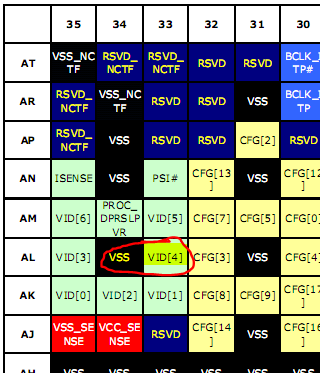
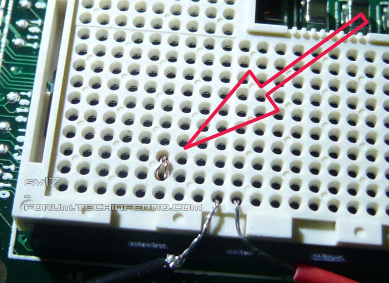
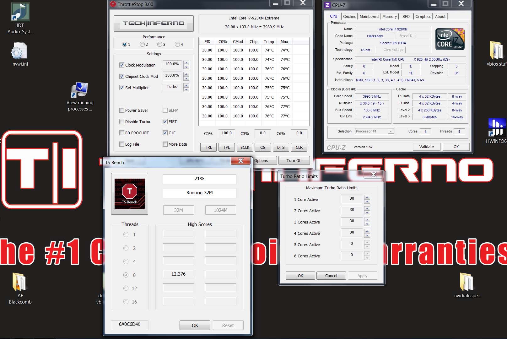
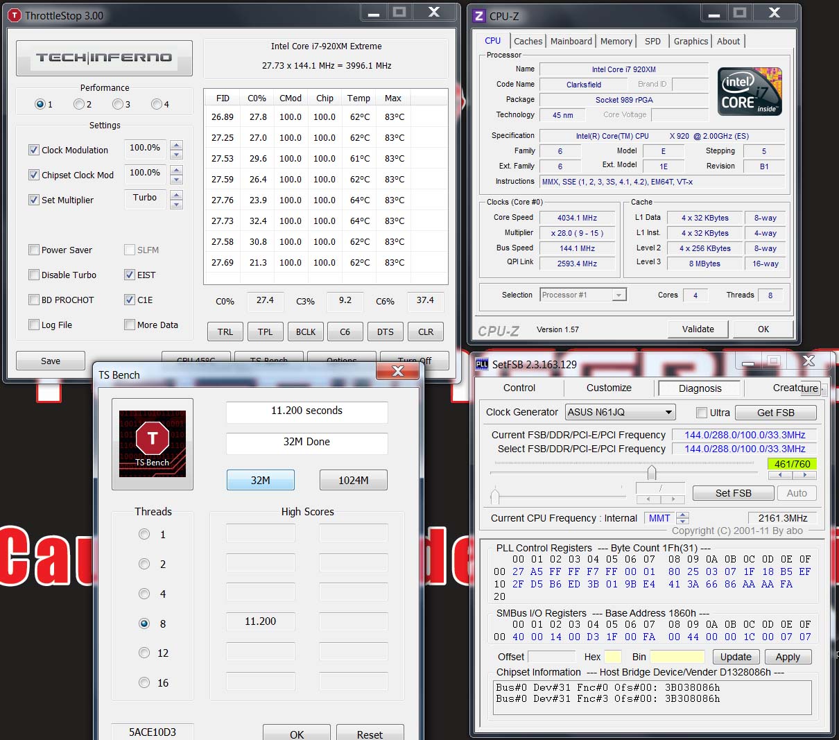
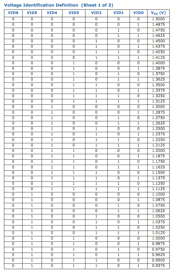
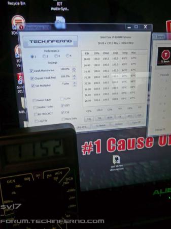
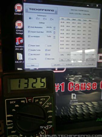
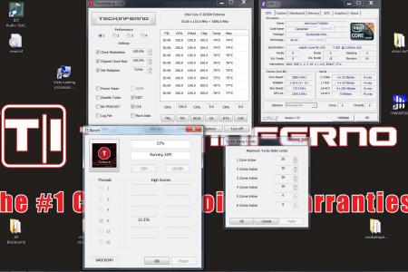
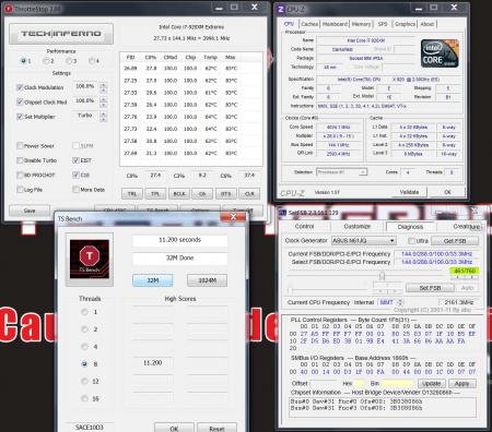
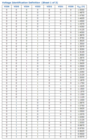
This post will quickly describe a way to increase (and decrease) the core voltage of the CPU, I have to advise anyone against doing this unless you're aware of all the risk that is involved. First of all a quick summary of how the voltage regulation works in the recent Intel CPUs, if you want to see my results skip to the end of the post. The method described below is mainly interesting for unlocked extreme processors, it will allow you to push the multiplier a bit more without crashing the systems. If you happen to have an adjustable BCLK it may be helpful as well and should allow you to push it further than with the standard voltage (provided the RAM can keep up with the speed) A quick explanation: The core voltage (Vcc) gets regulated by combining 7 different voltage identificators pins (VIDs), VID0, VID1, ... VID6. Each VID has a different voltage value. VID0 = -0.0125V VID1 = -0.0250V VID2 = -0.0500V VID3 = -0.1000V VID4 = -0.2000V ... you get the idea. Simplified you can say the Vcc is at 1.5V when no VID is active, every active VID pin will subtract it's value from the Vcc and in this way create the needed Vcc. Looking at the VID table should help to understand the concept. A 1 represents an active VID, a 0 an inactive VID pin. The seven VID pins allow a wide variation of different voltages which allow smooth transitions and can get easily controlled with a simple binary code. E.g. the string for 0.9250V would be 0101111 Now if you permanently deactivate a VID pin by connecting it to Vss (CPU ground), you increase the voltage of each possible VID combination which uses this pin actively (set to 1). This means with this method you always change a whole range of different voltages. For example if you connect VID3 to ground, you will increase each voltage which contains VID3 = "1" in the table by 0.1V. The problem is that this will result in voltage jumps when the CPU adjust its voltage. As an example lets assume VID3 is connected to Vss (this means VID3 is always = "0" in the table) Now if you look at the VID table, 1.1000V is a VID combination of 0100000. If the CPU increases the voltage by 0.0125V it will set the VIDs to 0011111 which normally results in 1.1125V, but since the VID3 is always set to "0", the voltage will directly jump to 1.2125V. Intel actually requires a smoother voltage transition, only 12.5mV steps are allowed according to the datasheet. This voltage mod will result in a "jumping" Vcc each time the modded VID pin should get set to "1". So this mod won't give you a voltage increase in a percentage basis, but only increase it at certain VID combinations. Therefore it's (in my opinion) only suited for increasing the max voltage, or (with some adjustments) also for decreasing the idle voltage. Anyway, this will result in voltage changes that aren't conform with the Intel standards. Also if you plan to do such a mod, I highly recommend to measure the voltage of your CPU before doing this. Intel says that "Individual processor VID values may be set during manufacturing so that two devices at the same core frequency may have different default VID settings", this means that the max voltage of your processor may be different from my value. After measuring the max voltage which my 920xm uses when pushed to it's stable limits (multiplier at 26x at all cores, baseclock at standard 133Mhz), I took a look at the VID table in the datasheet of the processor. My max voltage was at about 1152mV. This means by setting the VID4 to "0" (by connecting it to Vss) it gives me a boost of 200mV when my CPU gets to its limits. The datasheet provides all the necessary information about the pin locations. Below you see how it looks, encircled in red is what must get connected to permanently set VID4 to "0". For doing this you simply connected the Vss and VID4 pin in the CPU socket with a very thin wire. Make sure the CPU pin has still enough room. If it's done it'll look like this: I measured the voltage to make sure it worked as intended. The left picture shows the voltage a multi of 26x on all cores before the mod, the right pic the voltage after the mod. I didn't do a lot of testing yet, but the results are very impressive so far. I've been able to raise the multi to 30x on all cores an run a quick TS bench. And with a multi of 28x and a BCLK of 144 MHz I was able to run the 32M TS bench at more than 4GHz on 8 threads. The previous limit was 26 on all cores. Left: Check out the multi shown in Throttlestop Right: 32M TS bench at 4GHz on 8 threads I'll see what I can do with proper cooling... this is gonna be fun _______________________________ A voltage increase will result in an extreme increase of the power draw, resulting in a lot of heat. I have to advise everybody against doint this unless you're really aware of the risks involved in this. This is nothing that you should do to your machine permanently, but it's great to see how far it can be pushed. It's an extreme kind of overclock which will stress the system very hard. The Intel "absoulte maximum rating" for the voltage of the 920xm is 1.45V, so this is really close... _______________________________ As already mentioned, this method can also be used to decrease the idle voltage. You'll need to find out your idle voltage and then check the VID table for the suitable mod. You'll have to connect the VID pin(s) to Vcc instead of Vss if you want to decrease the voltage (set the VID permanently to "1") There are other possibilities to increase the voltage, also to get a certain percental voltage increase which won't have the problem of jumping voltage values. I might investigating in this sometimes. The advantage of this mod is, that it's very simple. No soldering iron is needed and it can be quickly removed. ______ Let me know if something is unclear, this is quite complex to understand and I wanted only to quickly explain the idea behind this. I'll be glad to help you in case you want to under- or overvolt your CPU with this method and have some questions. PS: I'll try to put this in a frontpage article when I find time.


 1 point
 -
Thanks Stam for taking me back to my hair day, Scorpions is also one of my favorites band. here is a good Aussie band,1 point
-
(now the bad news) the secondary port for the optical drive is a sata connection however it's only at Sata 1 speeds. So.. My corsair nova 64 is getting right at 150 and that's it. Still "almost" twice the speed of a 7200 but still makes me mad. The m14x doesn't have a raid style controller that I know of. I've spoken to the techs as I was concerned about the sata 1 speed from the optical port and they said it's standard for the m14x. I had to order a special bay (titan god posted the part). So I ordered on ebay and it works pretty well. Best wishes, StevenX1 point
-
Ok, it works again!! Back from the dead Didn't need to reflash, not sure what solved it... I used CCleaner and reseated the card, now everything seems to work fine, I just installed the 11.7 driver. Thanks everyone for your input and support!!!1 point
-
That would be me1 point
-
Time for some Aussie flavour They're not strictly speaking Aussies, but we like to claim them anyway1 point
-
1 point
-
so when using this paste make sure to protect yourself, please use asian condoms.1 point