Leaderboard


Popular Content
Showing content with the highest reputation on 11/03/12 in all areas
-
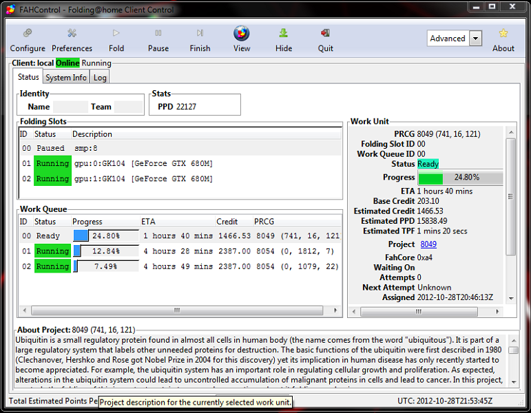
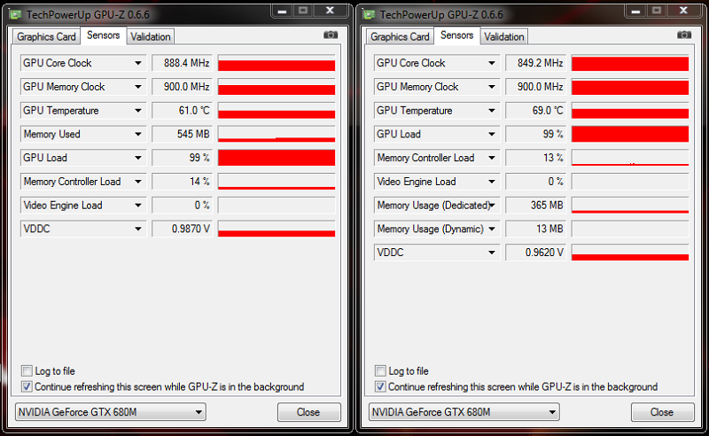
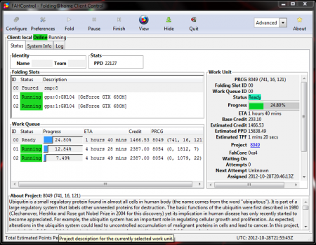
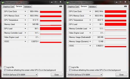
For anybody interested in another stress test, Stanford recently updated their assignment servers with the Dell GTX680m device ID's. I've been getting a solid 22,000 PPD using both cards. 24/7 stable and running cool on 850 base ROM (no OV or OC).
 2 points
 -
. So... Dell/Alienware managed to confuse a lot of users with their latest BIOS updates from last week. Version A08 of the M14x R2 as well as the M17x R4 and also A07 of the M18x R2 made a quick appearance on the Dell support site, only to vanish again shortly after - apparently to be replaced with A09 respectively A08. To make the confusion perfect, Dellienware once more decided not to publish any change log, not even a tiny bit of useful information. (I already bothered some Dell reps with this, but no success so far... they're always telling that my emails will be forwarded to the proper people...). Anyway, even though severe, I don't want to discuss the change log problem at this place. So what's up with those new BIOS? It's hard to miss that some numbers are missing between the last bios update and the current releases. Anyone who's slightly familiar with software updates and naming will realize that this is already and indication that quite some changes have been made - obvious, right? Huge parts of the firmware got revised and new modules were added as well. To keep it short, the bios (or UEFI to be more precise) is now officially Windows 8 ready. You may have already read that Microsoft requires the OEMs to have certain functions in the UEFI available (namely Secure Boot) in order get the systems 'Windows 8 certified'. Just to quickly clarify something, you don't need a 'Windows 8 certified' machine in order to run Windows 8, neither do you require Secure Boot, but the OEMs are pretty keen on this certificate as customers seem to prefer systems with certain stickers on them. What's this Secure Boot stuff? And how does this affect me? Secure boot is a protocol, a part of the UEFI, designed to ensure that a system gets booted in a so-called trusted state. This means a state that is known to be secure, that the firmware code has not been tampered with and is a direct copy which comes from a trusted source (e.g. the manufacturer of the used UEFI variation). Secure boot handles this with a system of different functions and interfaces as well as a key system. It makes sure that all external images have to pass a predefined authentication before they get executed. It is designed to prevent attacks which target the firmware to OS handoff. What secure boot won't do is protecting the firmware from direct attacks, e.g. manipulated bios updates and similar ... and this is where we come to secure firmware updating. Some of you may have noticed or read that coming from an 'old' bios version it is no longer possible aynmore to (easily) downgrade to an earlier version once you have flashed A08/A07 or later. This is because Dellienware decided to implement a way to verify firmware updates, in the case of the Insyde UEFI it is 'secure flash'. The UEFI image, the drivers which are required at boot etc. are all digitally signed. Now if you want to update your BIOS, this is what happens (simplified): - Flash utility checks the firmware image for integrity. - If ok, the image gets sent to the system - System reboots, starts the pre-uefi environment and starts the authentication process on the file which is to be flashed - If this check passes, and only then, the software environment for the flash gets launched, firmware gets updated. I have to admit that secure boot without implementing a method for secure firmware updating makes pretty much no sense at all, so it's obvious that this would come sooner or later, especially with Microsofts requirement for the Win8 certification. The consequence of this is that the user gets locked out of his own system. A (hobbyist like me) is no longer able to tweak the firmware of his system in order to use hardware the way he wants. Same goes for benchers, power users, hardware enthusiasts etc. who like to flash a modified bios in order to get access to disabled settings or activate certain CPU extensions which the system manufacturer locked out. The digital signing which gets used in UEFI is really sophisticated, so don't even ask about creating own signatures or revers engineering it. This is the end of bios modding (and especially easy flashing) as we know it. While I have hope that it will be able to find some workarounds for the current AW systems, I have reasons to believe that it will be much more difficult to achieve this with a system which comes with the secure boot function implemented by stock. One thing is for sure, if you intend to use a modified firmware, secure boot needs to be disabled ...but it is obvious that the issue with the secure firmware update (in our case 'secure flash') persists, even with secure boot turned off (for the reasons mentioned above). I don't want to read all this / To much technical details, what are the conclusions of all this for me? Do you use / want to use a modified bios on a current AW system (M14xR2, M17x R4, M18xR2)? If no - doesn't really matter for you, just go ahead and update to the latest bios which Dell provides for your system. If yes... - If you're still on an 'old' BIOS (pre-A08/A07 when looking at the official releases) then you can for example stay there and flash forth and back between a modified and stock bios, as long as the stuff you flashes predates A08 respectively A07 (again, I'm only talking about public, official releases). If you want to update to the latest version, keep in mind that you won't be able to easily downgrade anymore once you're on one of those new bios. You won't be able to easily flash a modified version either, unless you directly flash a modified when coming from an 'old' bios. In this case the mod will flash fine, but the consequences are the same, you won't be able to downgrade anymore easily, neither will you be able to just flash a newer modified bios. And if you already flashed a unmodified new bios and want to get a modified one... shit happens. Contact me in the corresponding thread of your model and we might be able figure out something. Let me know if you have any questions, some explanations might not be sufficient if you're not a bit familiar with all this stuff.1 point
-
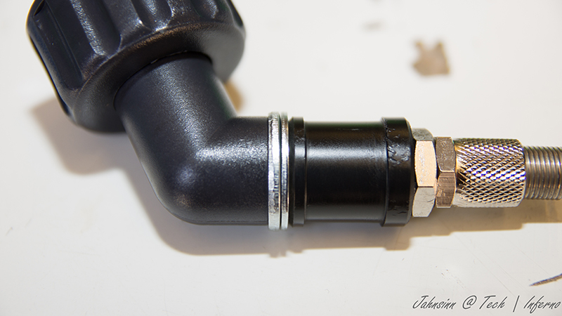
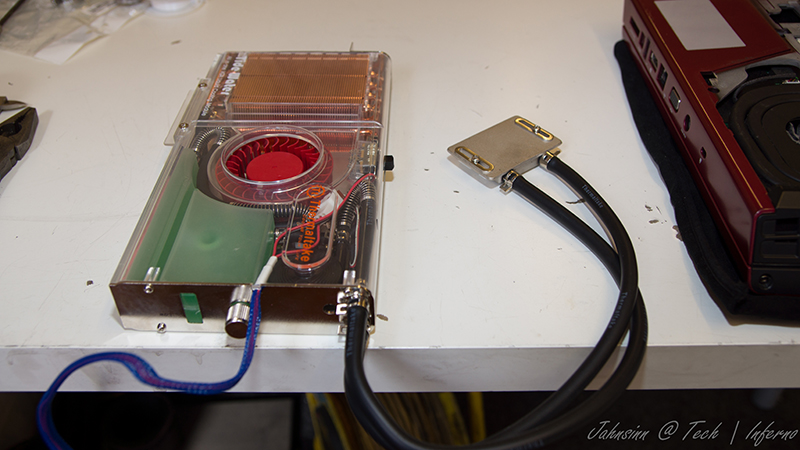
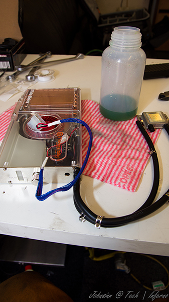
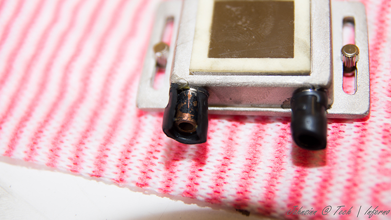
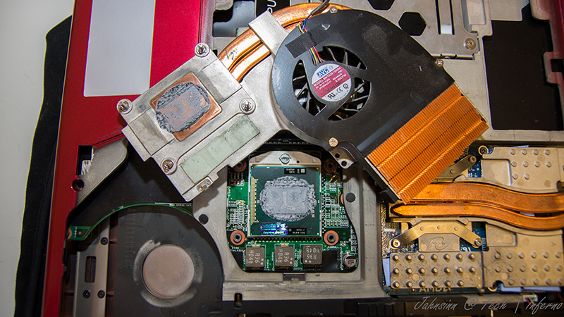
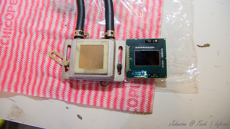
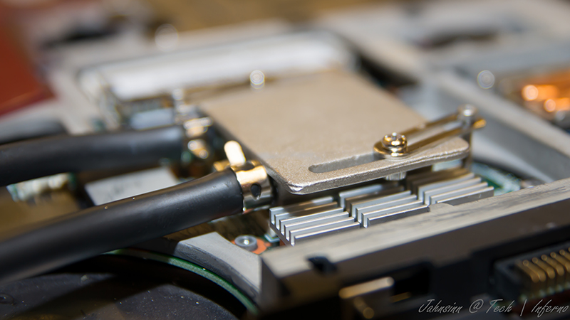
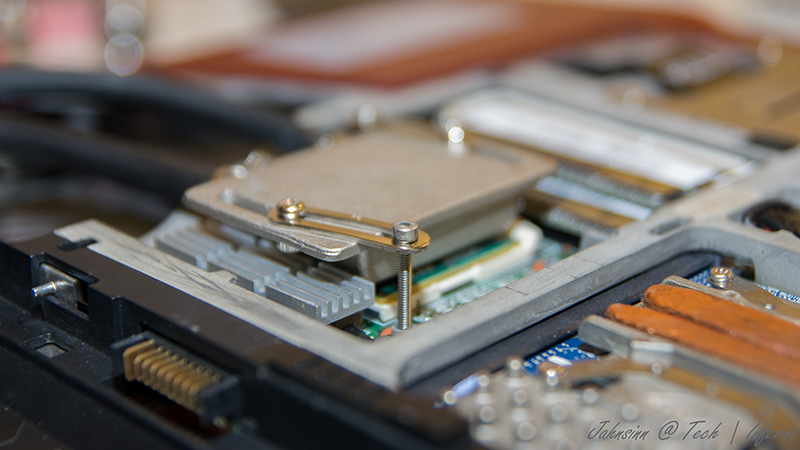
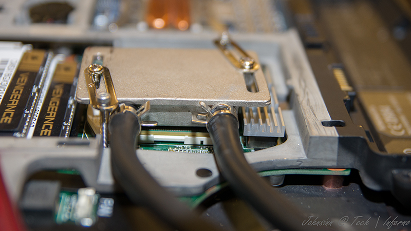
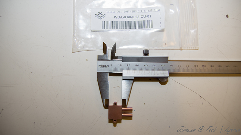
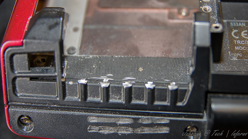
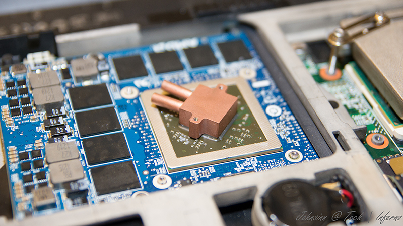
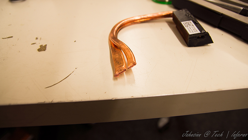
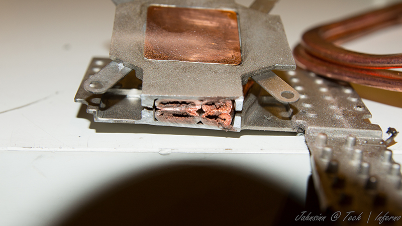
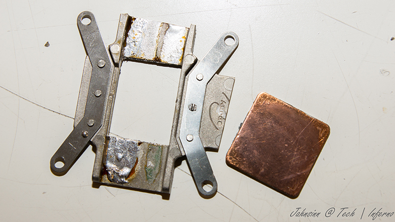
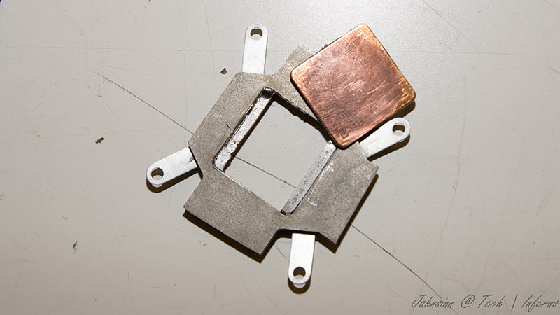
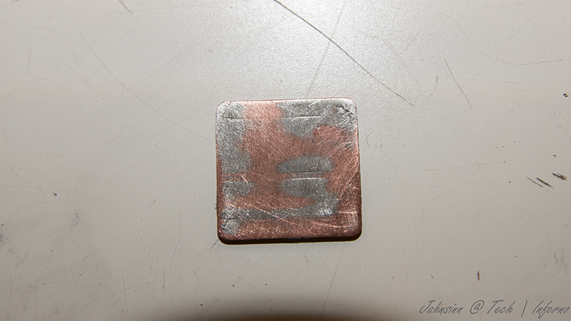
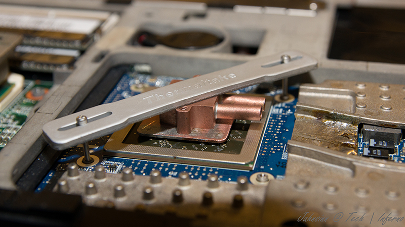
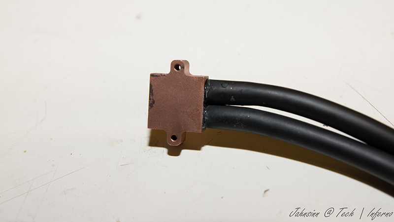
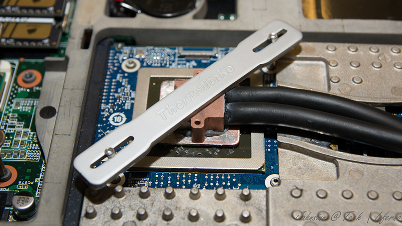
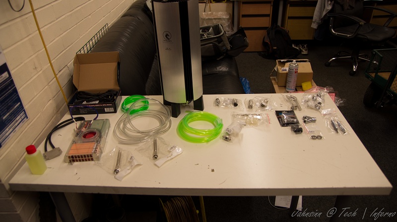
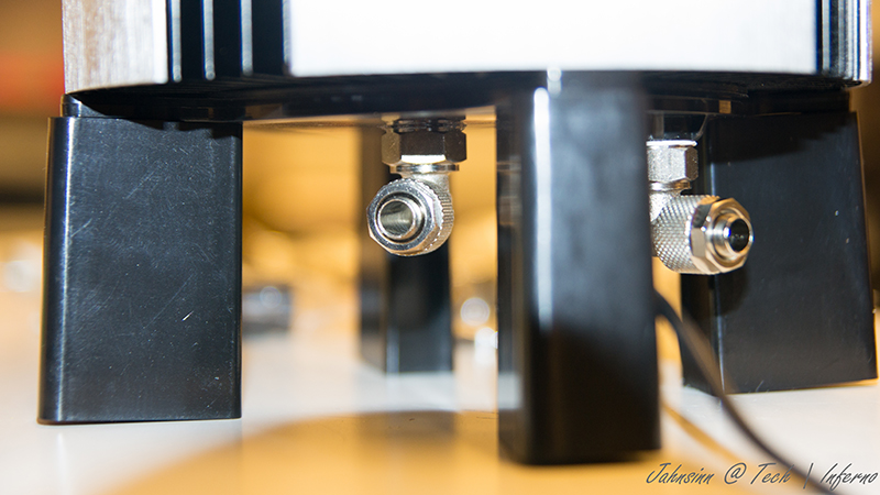
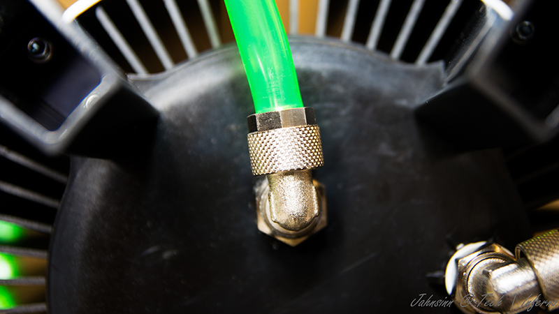
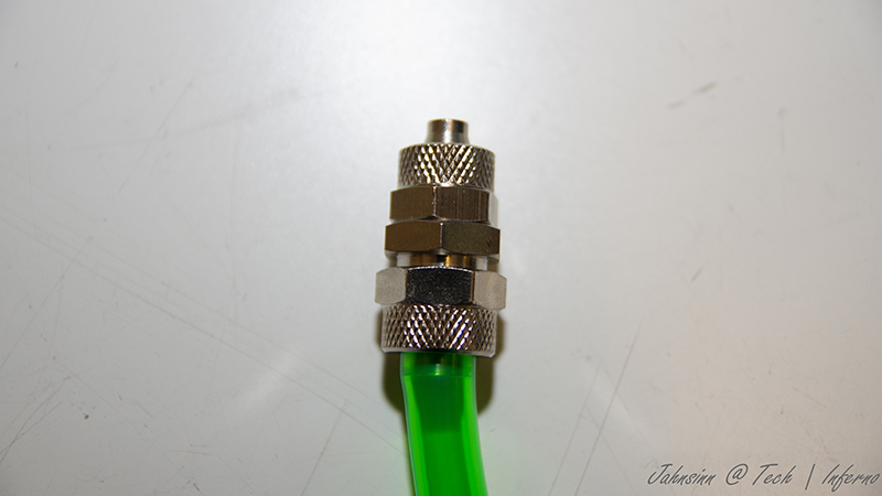
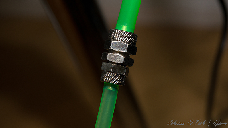
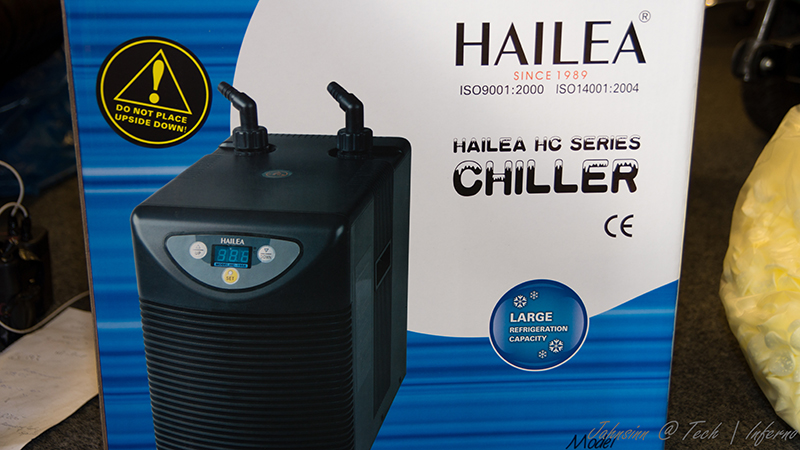
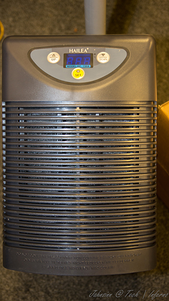
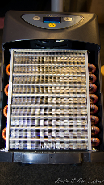
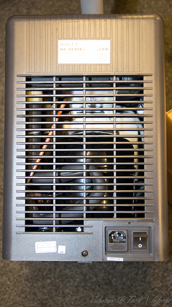
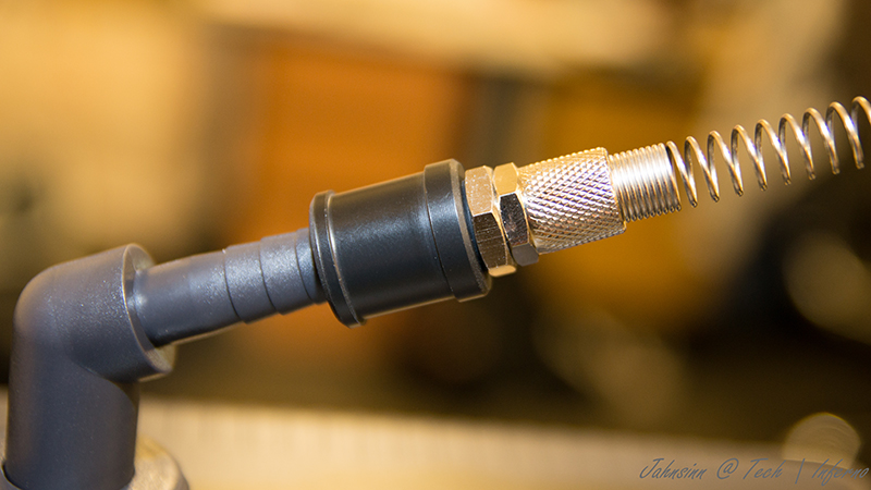
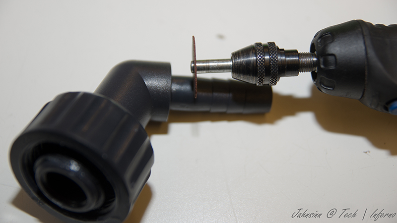
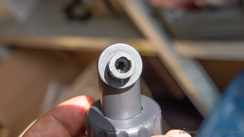
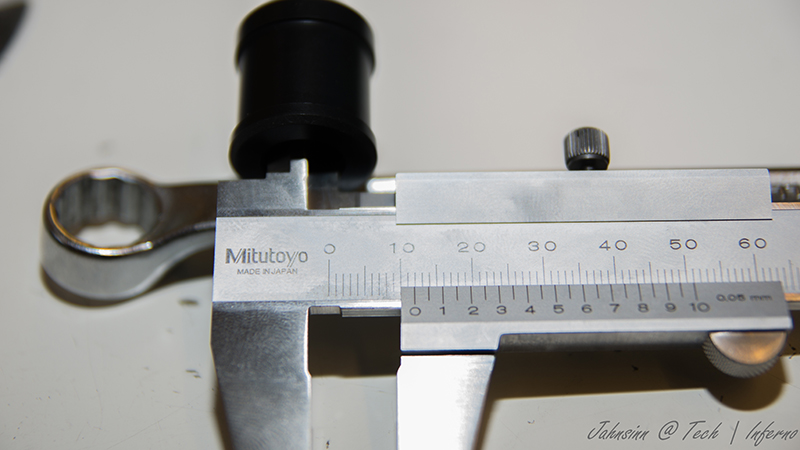
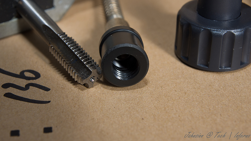
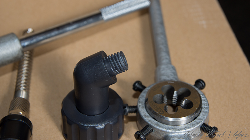
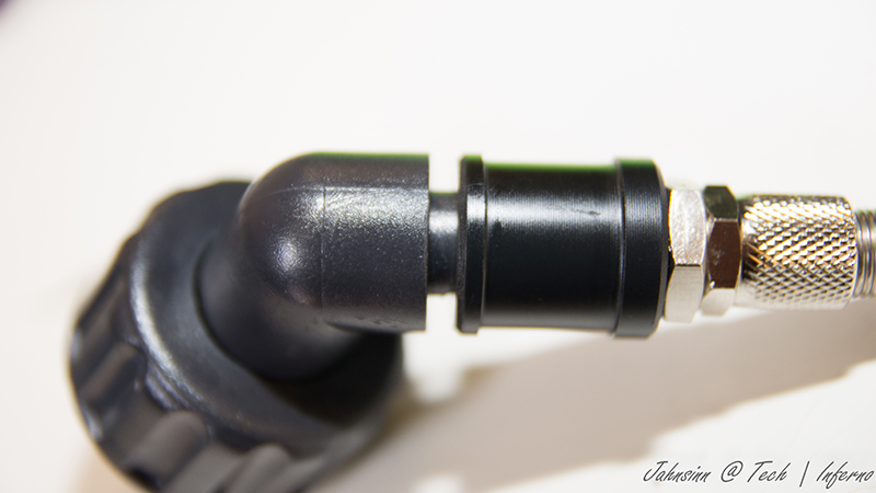
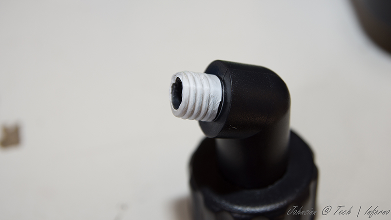
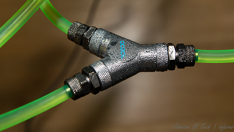
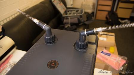
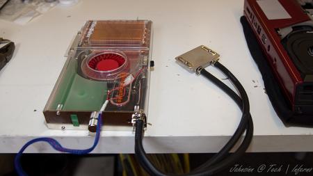
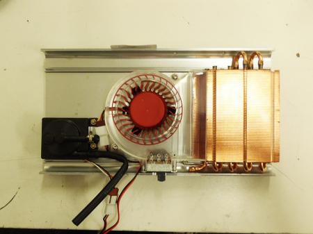
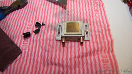
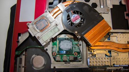
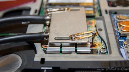
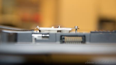
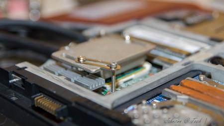
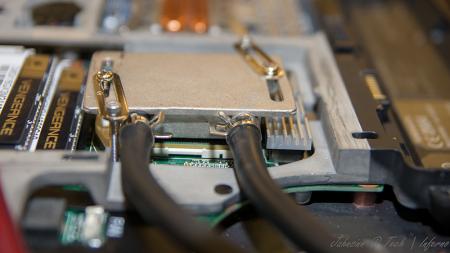
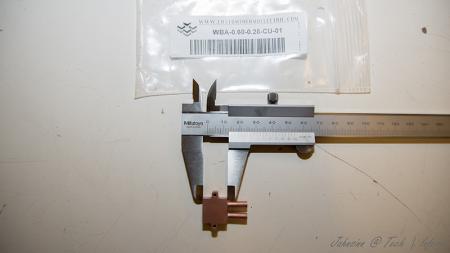
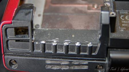
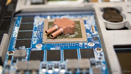
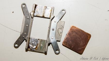
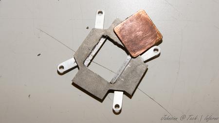
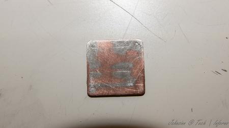
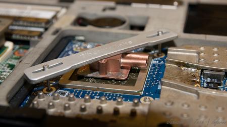
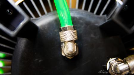
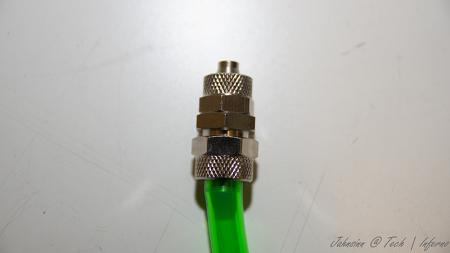
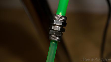
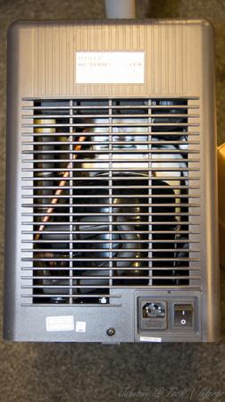
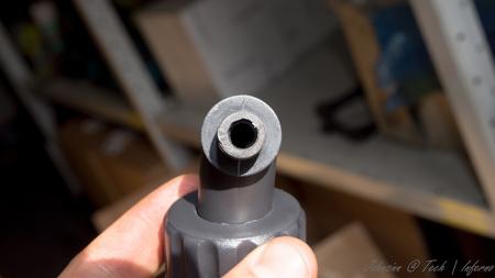
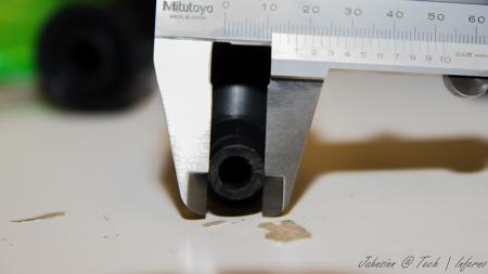
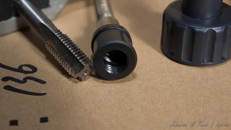
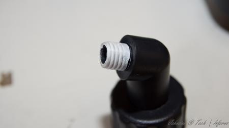
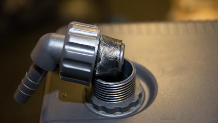
First of all, let me say I haven't finished yet. I'm still working on it and will update this thread from time to time due to much work at the moment. When I fitted my 940xm and the 7970m I got really mad of the heat and the fan noises even in idle mode. So I decided to get it all cooled with a silent, most important quiet, external water cooling system. I checked the internet and found evth I need to get it done. The most difficult thing was to find slim water blocks to cover the dies. I will list all the parts I used with article number and website if you're interested at the end of this post. First the overview. These parts are going to be used: Actually not much, so let's start. I start tubing at the inner hose socket of the reserator. This is the place where the pump is placed behind. You have to use a 10/8mm hose. By this, 10mm means the outside diameter of the hose, 8mm means the inside diameter. This is very important to know by everything you do on water cooling systems due to different fittings, barbs or reducers. Fit the hose and tighten it well with a spanner. Now you need a reducer to get on a 8/6mm hose. This is necessary to get in fitted to the chiller. At the other end you need to fit the 8/6mm hose. After this is done the 8/6mm hose leads into the chiller. A chiller pushs down your temps to a predefined value set by you, the minimum you can get theoretically is +3°C. Basically you can say it works like a refrigerator. This is very helpfully when you start gaming or other intense work on the laptop to keep the temps low. Here are some pics of it. To get the hose fitted the first custom made had to be done. Maybe I didn't know how it actually works, but I had no clue how else to do it without a modification... As you can see on the picture, the 1/4" adapter didn't fit to the chiller's nozzle. I really don't know what's the original idea by the developers. So the first adjustment had to be made. Cut the end of the nozzle as you can see on the pic. When this was done I noticed really pour casting quality inside the nozzle. This would massively reduce your flow speed. So I used a drill to get it out. Finally I got an outside diameter of 13mm at the nozzle. The adapter has 12mm inside diameter So just perfect to cut a M14 thread to both parts. Unfortunately I couldn't get closer due to the layout of the die. two washers solve this problem to get it proper tightened. To get it proper sealed I used teflon tape. Just the best way to get something sealed. Don't do it without any sealing! Use some Vaseline before you stick in the nozzles. Do the same with second side of course. At the end it'll look like that. Let's get to the CPU water block. I purchased the Thermaltake CL-W0052 Tide Water, originally made for desktop PCs to cool down the graphics card, on ebay to get all the stuff I'll need to do it. I chose that one because the water block has just a height of 8mm. Also all the hoses and clamps will be helpful. First drain the coolant. Then I opened the chassis and robbed all hoses and clamps. You'll need them in a couple of minutes. They're all bonded quite well, so just cut them at the ends. I also cut and removed the hoses of the water block itself, just to make sure everything is okay. I didn't want to get upset when I filled the system with water. So I cut them and removed the old adhesive. I then removed the original cpu heatsink and compared the die with the water block The water block as it was out from the box was just a touch too small to fit correctly onto the die. So I just removed the tape around the block. Now it was ready to get fitted. All I needed to do was loosing the existing bolts on the water block and tightened it with M2.5x20 hex nut bolts into the existing holes. At the end it looks like that. By the way, the mosfet heatsinks came with the tide water vga cooler. I also fitted the black hoses as they were, just without the glew and it still seals perfectly. To get the hoses guided out of the laptop you need to remove your fan control at the back of your laptop. When you're doing this, be careful not to touch the chassis as I did with whatever you use. I used the dremel and didn't see it for a while. What a shame! Nevermind, so let's get over to the gpu side. I bought a very tiny water block with just 15x15x7mm dimensions to not to exceed the height. So may be later I will be able to fit the backplate cover again. The water blocks would actually fit on the die, perfectly. But due to the layout of the gpu die the block just fits in diagonal postion. So useless for me. To get the water block in the right direction I unsoldered the copper plate of the original heatsink. That one has got the right dimensions to get this solved. Clean the copper plate from the old tin on top by using the Dremel or sandpaper. At the end that's the way it should work. Just to mention, also the holder came with Thermaltake tide water cooler. The bolts I bought seperatly on ebay. They are M1.6x20 but too long, so I cut them down to 15mm. Now they fit into the existing holes and push down the block properly Use now the -->small<-- black hoses robbed from Thermaltake chassis. These are the inside hoses, they're smaller. You need to use some adhesive because the clamps coming with the hoses are just a way too big and don't keep it tight to nozzle. Now just add some thermal paste between copper plate and die, and copper plate and water block. Tighten it all down. Finally it looks like that. [ATTACH=CONFIG]5105[/ATTACH] hoses leaded through the fan grill, gpu side. I mention again, just temporarily cause I'm still waiting for parts. in progress... [ATTACH=CONFIG]5107[/ATTACH] [ATTACH=CONFIG]5106[/ATTACH] cpu side [ATTACH=CONFIG]5108[/ATTACH][ATTACH=CONFIG]5109[/ATTACH] The hose laying is actually just in common sense. Nothing particular I should mention. Reserator -> 10/8mm hose -> 10/8mm to 8/6mm reducer -> 1/4" compression fitting -> 1/4" adapter for chiller -> chiller nozzle -> chiller -> nozzle, adapter, fitting -> 8/6mm hose -> Y-splitter first end hose -> 8/6mm hose -> quick coupling -> black hose (termaltake tide water) -> cpu block inlet-> cpu outlet -> black hose -> quick coupling -> 8/6mm -> Y-splitter second end hose -> 8/6mm hose -> 6mm barb -> small black hose (thermaltake tide water) -> gpu block inlet -> gpu outlet -> small black hose -> 6mm barb -> 8/6mm hose -> Y-splitter | Y-splitter -> 8/6mm hose -> 10/8 to 8/6mm reducer -> reserator update in progress...


 1 point
 -
Dell support says a lot...1 point
-
Its amazing I haven't found this place until now. All the different discussions and applications are proving to be super interesting and helpful.1 point
-
Joined site the other month on my tablet. Good old username typo. Regardless TI has a wealth of information and very intelligent users including hardware hackers. Great place to pick up info. I don't post much but I have occasionally on nbr and xda. Will continue lurking and reading the threads here on TI Sent from my DROID BIONIC using Tapatalk 21 point
-
Hi I am new here. Starting my computer science degree and just learning from the forum. Thanks everyone for the input I am learning a lot!1 point