


Zakyn
-
Posts
31 -
Joined
-
Last visited
-
Days Won
5
Content Type
Profiles
Forums
Downloads
Posts posted by Zakyn
-
-
@Swung Huang Good job! I am happy to see you are going to manufacture adapters for everyone. I will not be able to do that, my adapter works but my motherboard died (not caused by adapter, just one of the mosfets for bios shorted). So even if I can manufacture them I have no way to test it so I decided to buy new PC and leave it all behind. I think I will post all of my desings if anyone is interested.
-
Can anyone with modded bios send me exact settings from each card in bios menu please? I really dont know how to solve psu power off issue. I tried other power lanes of ultrabay but there is no voltage, maybe they depedns on some other signal. Last thing is to try original bios.
-
On 4/7/2019 at 8:56 PM, High_Voltage said:
Hm, I don't see any difference to my own schematic I made following Gerald's designs.
Can you measure PSU_ON voltage with the laptop on and off? Does it always stay 3.3V, or could it be that it drops, but not completely to zero?
In order to set aside any suspicion on BIOS settings, you could try with original BIOS and an AMD card, for example. Or with Nvidia, and just wait until the laptop powers itself off-
So I did some tests.
1) power off with charger and measure the transistor gate voltage (before the resistor) -> still 3,3V
2) no effect if gpu is inserted or not3) tryied various bios settings, nothing seems to help
4) if the charger is plugged back in psu wont switch back on
I cant find any bios setting which could influence it. Any advice welcome. -
As soon as I solve the power issue (PSu stays up after laptot is off- if laptop is on charger), I will make 10 adapters. I hope I order PCB within the one week. Price will be 100 USD plus shipping.
-
On 4/4/2019 at 4:23 PM, High_Voltage said:
Try disabling wake-on-LAN if it is enabled.
Also, if you share your final schematic, I could have a look.
Zakyn_eGPU_v3.pdf not much changes since last version
")
-
Adapter still works, my design is on 2 layer PCB. So maybe it enaugh and high impedance 4 layer PCB is not needed. I can make some last mods (I want to make PCIE power traces wider) and order like first 10 PCB at JLCPCB.Right now I have only 5 Ultrabay connectors but if there will be enaugh interest I can order more of them and produce more adapters.
There is only one think in my conserns, that is: If I turn laptop off PSU is still up until I unplugg laptop power supply. Do you know about some bios setting which could cause it? -
13 hours ago, jamesrule1 said:
Thanks.
Parts are obsolete.

I saw the other user has its own version. I wish they share it.
I use the same parts as gerald. If you search deep there are still some shops where it is possible to buy it.
-
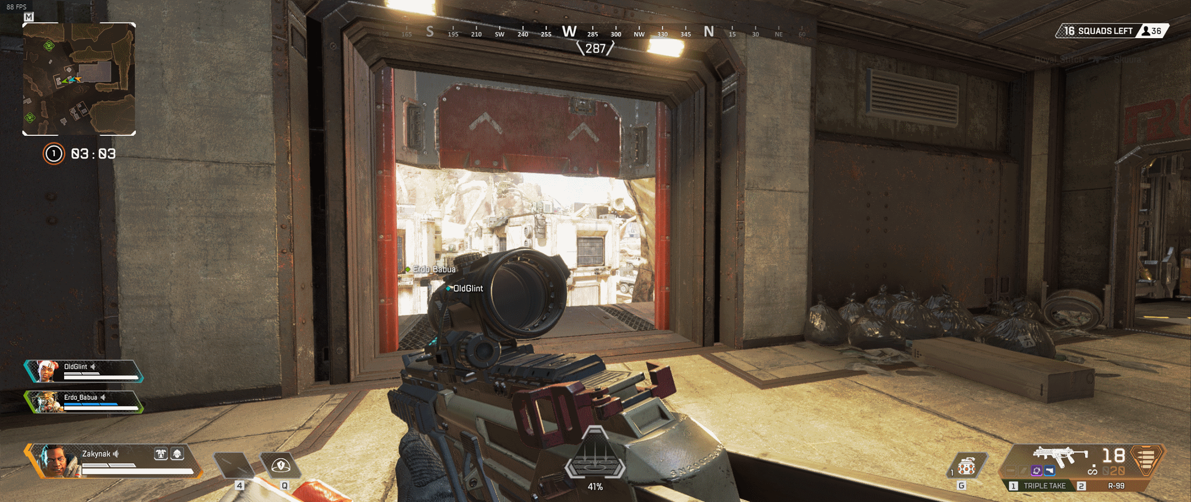
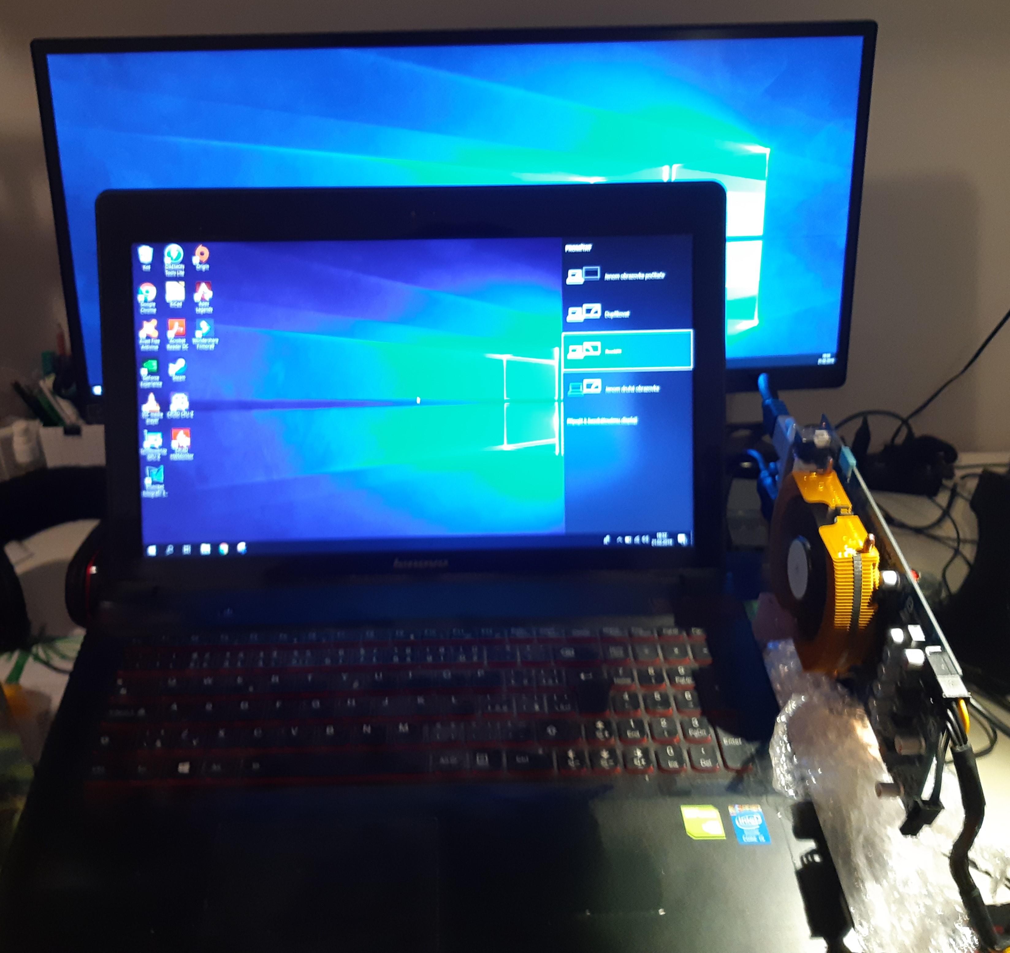
Great news, my version 3 is working stable
Now I want to do same case for it.
I finished yesterday in the night so I only tested Apex legends for 1 hour. See screenshot. (80-90 FPS stable) Ultra settings (2560x1080).
GPU: RX 580 8GB NITRO+
-
 4
4
-
-
21 hours ago, Bodnet said:
what about now, do you have adapter?
can it work without external monitor?
Yes it is possible, someone already posted it before.
-
Update: I bought RX580 8GB NITRO+ and now it crashed into impedance problem which @High_Voltage warned me before. So next version (hope final) is in the progress :D. RX580 is working fine, but when it is under load (benchmark, game, etc.) FPS drops occurs and game sometimes crashes.
-
If I count material only I spend something about 50 EUR. Plus lot of work
 Yes, I agree my next approach is to make some kind of case for it and also I would like to do better version with cable extension to put it somewhere away from laptop.
-
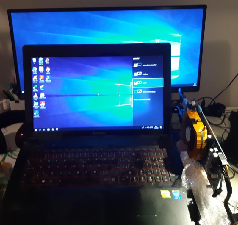
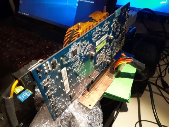
Hello guys,
I have some good news My adapter is finally working Here are some screens and photos. I will add more as soon I get better GPU. GPU-Z output is somehow wrong in some info, but I think it is caused by old GPU.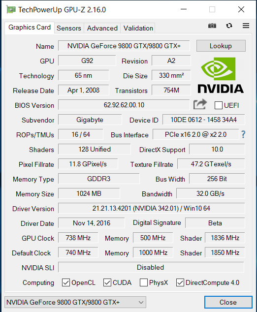
-
13 hours ago, High_Voltage said:
Oh, I was talking about the connector that the gpu is inserted into, not the ultrabay one.
Sorry. Yes I have checked that already, if signals really goes to right side and pin of connector. Now I will take a look on that GPU. Thank you very much for all of your advices. I will post some update as soon as I find some desktop where I can put my GPU.
-
1 hour ago, High_Voltage said:
The schematic looks good. I can't see any mistakes. Have a look at your PCB and make sure everything is routed correctly. One pitfall I could think of is the footprint for eGPU PCI-E connector. When you look at it from the top, with that smaller section facing up, the B will be on your left, and the A - on your right, which is counter-intuitive when compared to the schematic symbol.
Another question is whether you've actually tested that GPU with another computer to verify that it works?
I think I have the footprint right, yes its other way than on schematic. But I draw it as it was in datasheet.
Ye it came to my mind if it can be bad GPU. My friend told it work but guess I need to test it somewhere. I dont have any desktop at home.
-
1 hour ago, High_Voltage said:
Do you have a schematic of what you've built?
Double-check the pinout of pcie and whether all the signals are routed correctly. Check whether your Reset signal is ok.
Also, did you use a high speed PCB and if you did, did you calculate RF impedance of the differential pairs correctly? I think it needs 100 Ohms per pair. Anyway, if the issue was in signal integrity, I would at least expect the card to be detected, so the problem is somewhere else...
Also, are both 12v and 3v correctly supplied to the card's pcie slot?
Here is my schematic.
Zakyn_eGPU.pdf
I will check 12v and 3v power supply and re-check RESET signal. I didnt calculate RF impedance (that's beyond my knowledge - shamefully), but as you wrote if it was only about signal integrity I think card would be detected at least.
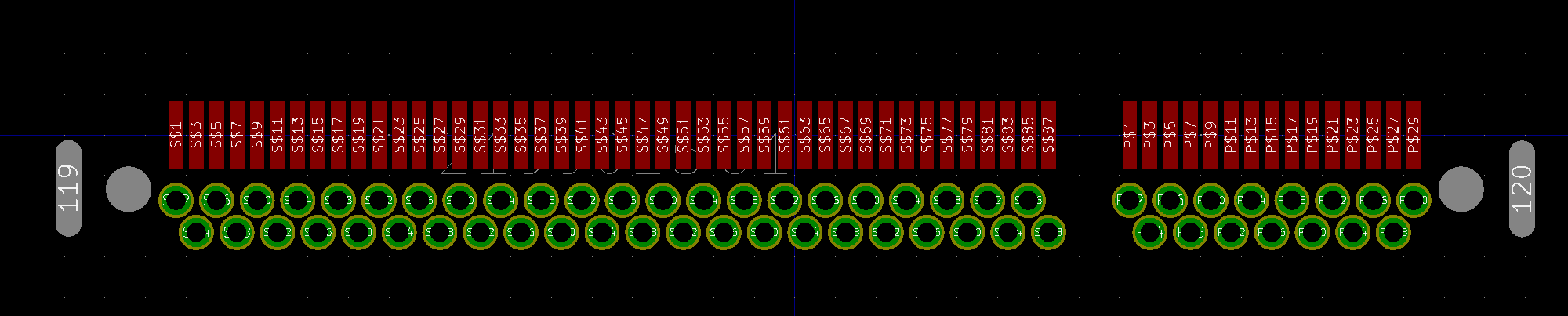
PS: Ultrabay connector has two pin numbers: one as in datasheet and second for Lenovo y510p schema (for easier orientation). -
Hi guys little update:
My adapter still not working and I don't know how to find a problem.
I've tried @gerald's pins for PWRGOOD and that one in Lenovo schema nothing worked.
I am using 9800GTX for test run after normal boot PSU is switched on, but GPU is not detected and not giving any ouput.
Differential pairs are same lenght... Signals connected according to @gerald's scheme (without some resistors, which @High_Voltage suggested not to use).
Not sure what to try next. Maybe @High_Voltage have some sugestions.
-
My adapter is soldered and currently not working. PSU switch is working, but GPU is not detected (PC working properly). I guess it may be some things which I made variable because the was difference between Lenovo's and gerald's scheme (like PWR_GOOD and PRSNT#1 pins). I will try some combinations and do some measurements, hope I it will be it.
Edit: Current configuration is by gerald's scheme.-
2
-
-
My version of adapter (PCB only) is at manufacturer. I think at one week I will have it and then I will solder all parts. After that I will try to run some GPU on it
Also my mPCIe adpater just arrive, I will do some benchmarks for comparison.
-
2
-
-
13 hours ago, High_Voltage said:
@Zakyn I'm not sure. Guessing that @gerald has experimentally determined that out of the two possible reset pins this one is the right one.
Actually, I'm also currently designing an Ultrabay adapter. In my design I decided to go for @gerald's choice of Reset pin, but pull it up to the standby +3V (pin 64 on Lenovo schematic). There is already a pull-up on the motherboard for this pin, I've added this one just in case. Probably going to try with this pull-up unpopulated first...
Ok, I will make some pads for 0R resistors to choose between pins. thanks for response
-
On 10/22/2018 at 9:05 PM, High_Voltage said:
Hi, @Zakyn, I had a look at your schematic. Not really going to check your routing to the PCI-E pinout, let's hope it is correct. Also, I hope that you are aware that the high-speed PCI-E lanes have to be routed in differential pairs with length matching (KiCad has a special feature for that) (also make sure to match the length among all the pairs).
Now, speaking of the necessary pull-up resistors on the Lenovo side, as it has already been shown by @gerald while I was writing this response, here's the situation with the additional resistors and circuits:
- 1k pull-up to +3V at pin 70 of the Ultrabay (pin SUSP# in Lenovo motherboard schematic), this is R4 in Gerald's schematic. (note that Gerald's schematic uses different pin numeration for some reason)
- R1, R5 and R6 are not installed on Gerald's adapter board, so you can just ignore them. These pins although labelled sensibly, don't appear to make any difference to ultrabay functionality
- R2 used to be installed in V2 of the adapter, but in order for it to work properly, this pin must be open. Do not install!
- 1k pull-down to ground from Ultrabay pin 94 (SLAVE_PRESENT#), this is R3 in Gerald's schematic
- Wire Ultrabay pin 98 (PLT_RST#) to PCI-E Reset pin, additionally pulling the signal up to +3V3 (that comes from your power supply)
To summarise, out of all of the resistors, you only need two (R4 and R3), plus the Reset circuit.
Also, you don't have to route SMB bus to the PCI-E slot as it is redundant. Better make solder pads for it so it can be used with my hardware mod.
I just did last check before making PCB and I see reset circuit (98 PLT_RST#) on gerald's schema is actually connected to S_DGPU_RST (pin 92). I am little bit confused which is the righ pin. Can you give me a hint please?
-
21 hours ago, MADNESSS said:
@Zakyn On the website you mentioned above, it says that minimum order is 7 pcs. Did you order 7 pcs, or there was possibility to order just one?
Wish you good luck in your project.
Yes, I have 7pcs. But I wanted more than one so its not problem. I already have one soldered in my first not working version
So I hope 7 will be enough :D.
This site was first where I was able to get less than hundred pcs.-
5
-
-
On 11/28/2018 at 7:58 PM, manolis said:
@ZakynHello, so did you finished the project? because i have ordered ub and will try to make it myself
Hi, I didnt have much time recently. I want to work on that during Xmas. I already updated my schematics and now I need to redraw a board. When I finish I plan to do some tutorial for everyone (if I will be successful
).
On 11/29/2018 at 8:53 AM, blackranger said:Hi Guys,
i have y510p i5 4200M, Dual GT750M , version
I recently ordered GDC V 8 Beast mpcie , but i know the GT/s is not good.
Just want to know whether cpu bottlenecks with 1060 or due to low GT/s of mpcie it doesn't affect ?
Any update on new production or updated version of ultrabay adapter?
I've seen some guys making their own, may i know where to get the parts ?
Thanks in advance
I got my ultrabay conenctor from: https://www.verical.com/pd/te-connectivity-power-connector-2199015-1-4586152.
-
1
-
-
@Swung Huang Looks great, is it your PCB available somewhere? Which cables are you using?
-
7 hours ago, Drozof said:
BTW now that we can use nvidia GPUs is it possible to use the internal GT750 at the same time? like for SLI or physx
It is not possible to use SLI for two different GPUs. You can use GT750M for native display on laptop and have it as second monitor.
Y510p Ultrabay Graphics card
in Lenovo
Posted
I found another solution of upgrading of y510p. You can just put all compents into this board https://rover.ebay.com/rover/0/0/0?mpre=https%3A%2F%2Fwww.ebay.com%2Fulk%2Fitm%2F133135412851.
I would like to do it myself but this sellier does not ship to europe.
I think is better solution with more potential.