coolane
-
Posts
30 -
Joined
-
Last visited
-
Days Won
3
Recent Profile Visitors
1796 profile views


coolane's Achievements
T|I Semi Advanced (3/7)
69
Reputation
-
Very nice! You made it even have better fit than mine. Back in that time I didn't bother spending too much time to sand it that much (only got 400 paper). My core still has a little bit gap with the heat sink, not perfect. You will be happy with the temperature dropped, it's gonna be significant.
-
Yup, I tried to be quiet. That's why I asked you to search google instead of posting his original url, and recommended you to wait for Prema's vbios at the beginning. I am waiting to switch back to Prema's vbios once is ready. Good job! I sanded it a very long time using the 400 grit paper. Maybe it will be faster and more efficient with a dremel.
-
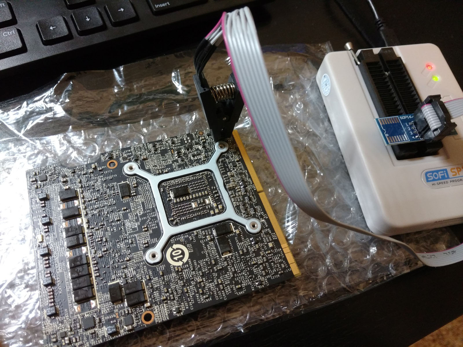
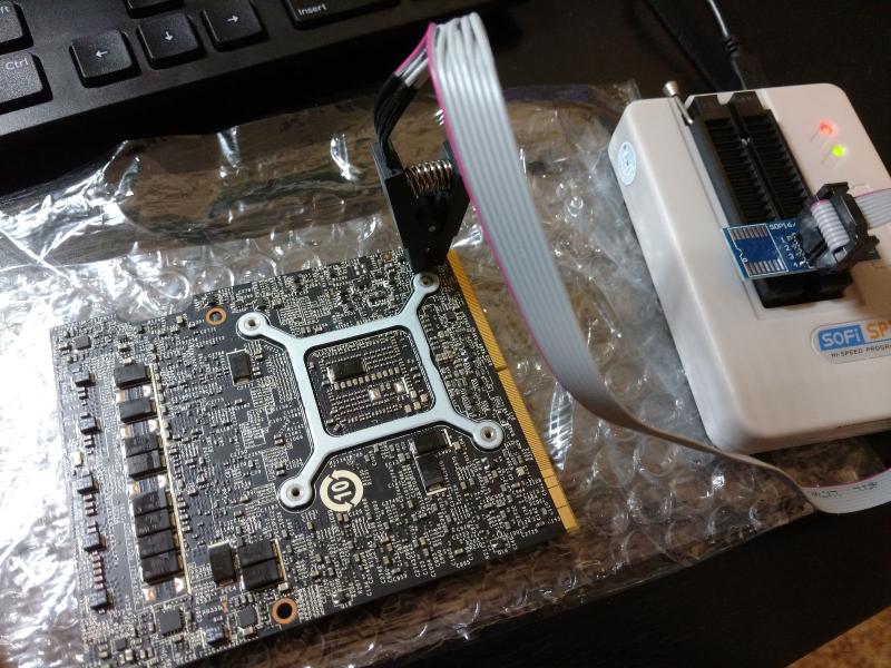
The vbios was modded, it cannot bypass the check of nvflash and will fail the flashing. Currently nvflash only supports vbios that is officially signed. I used a programmer to program the vbios into the chipset. The one that I used is starting with "Clevo_8", which is for P870DMx series. The one started with "Clevo_7" is for P7xx series.
-
I modded it according to the thread, but it resulted in black screen on boot. There is something wrong that I don't know. Right now the vbios that I am using was from a chinese forum (google "vBIOS硬刷 Pascal GTX1060/70/80"); it unlocked the TDP adjustable to max 200W TDP, voltage is still locked without control.
-
So in Dreamonic's thread, he used 150W for example to mod the TDP. 150W is 150,000 mW, in hexadecimal is 00 02 49 F0. In the vbios, you read it from the right to the left, so it's modded as F0 49 02 00 (as he highlighted as red). 200W is 200,000 mW, in hexadecimal is 00 03 0D 40. So in the vbios, it will be 40 0D 03 00.
-
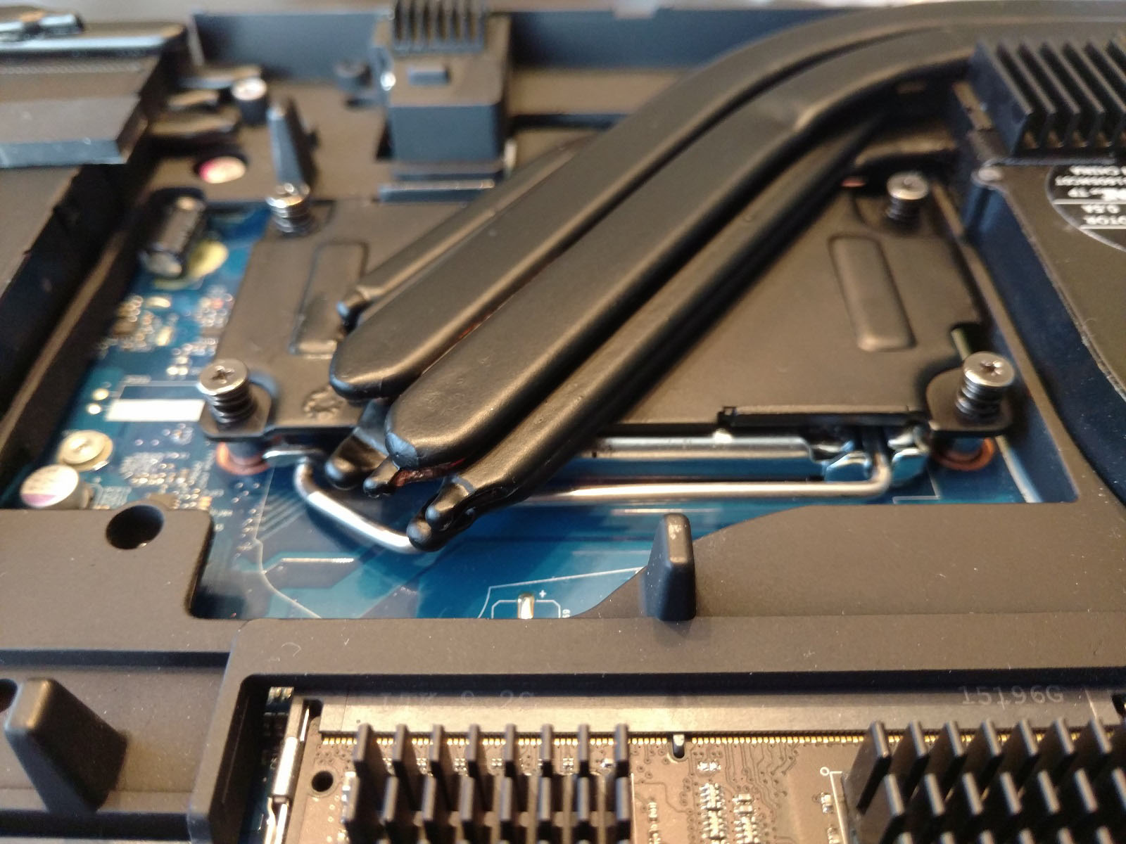
Separating the original pipes from the heat panel might damage the pipes or the heatsink, because they were soldered together firmly. The only way that I know it's to heat them up hot (~500 Fahrenheit or higher) enough to take of the pipes. I am not sure about this, you might need to do some research. Yes, I sanded the surface of the pipes around the core area to expose the copper partially, that way it can transfer heat better without having a layer of paint between them. Depends on the thermal performance that you are looking for, you can determine how much you want to sand out.
-
You're welcome . I'm glad it helped! I just simply used Arctic Silver Thermal Adhesive to attach the heat pipes on the heat sink. If you would like the best performance, you can consider soldering them.
-
This is the package I got from amazon: https://www.amazon.com/Mudder-Aluminum-Heatsink-Cooling-Raspberry/dp/B01GE7Q060/ref=sr_1_23?ie=UTF8&qid=1485027248&sr=8-23&keywords=heatsink They were designed for Rasberry Pi. I used the smaller one from the package, the size was showed as 8.8mm x 8.8mm x 5mm. Please PM me if you have further question. I feel like this is a wrong thread to talk about modding in details.
-
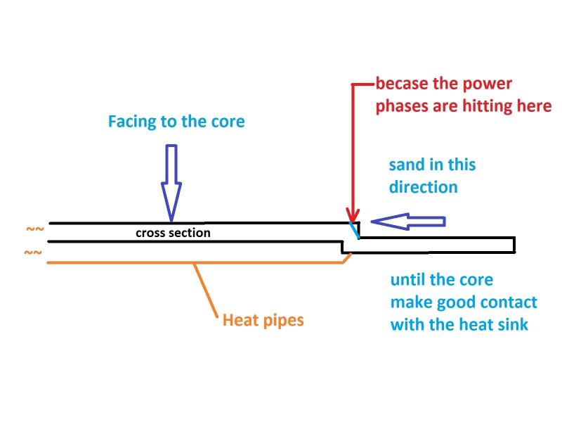
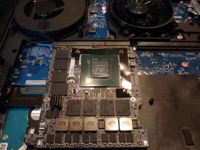
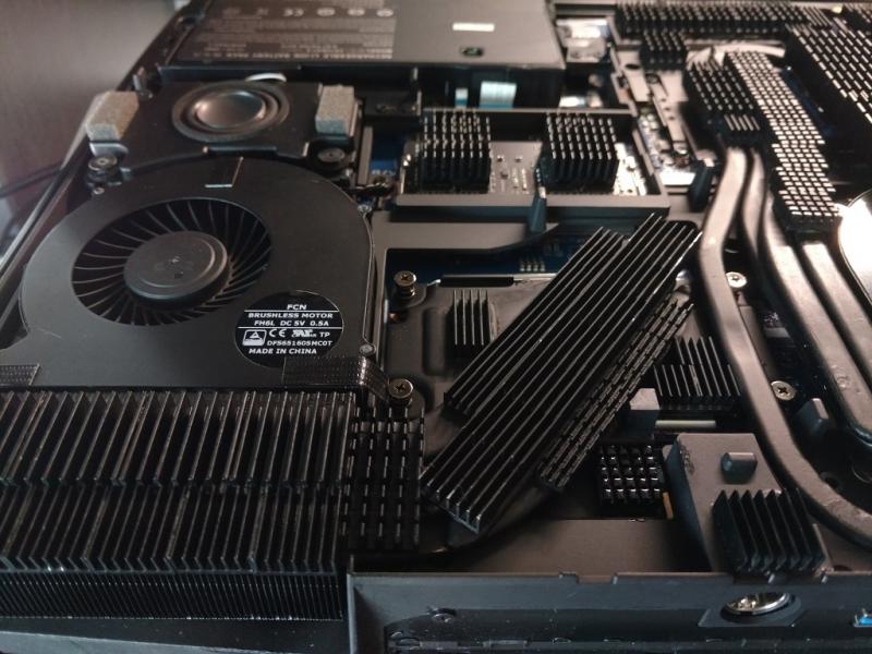
1. I just used a simple hacksaw to manually cut it and 3M sand papers to sand it; the saw looks like this one: https://www.amazon.com/Stanley-STHT20139L-Rubber-Grip-Hacksaw/dp/B00B5A0T5K/ref=sr_1_2?s=power-hand-tools&ie=UTF8&qid=1484799254&sr=1-2&keywords=hacksaw 2. Hopefully the below picture can give you a better insight. If you put the 1070 together with the 980DT heat sink, you will see a better picture of where to cut out or sand out. Because your goal is to have the core contact the heat sink evenly with 4 screw holes aligned. 3. Just 3M double sides thermal tape, it came with the small heat fins I got from amazon. If you don't plan to resell your card, you can use some thermal adhesive. 4. It's okay to have the red-circled components to touch the heat sink, I applied some thermal paste there to dissipate the heat.
-
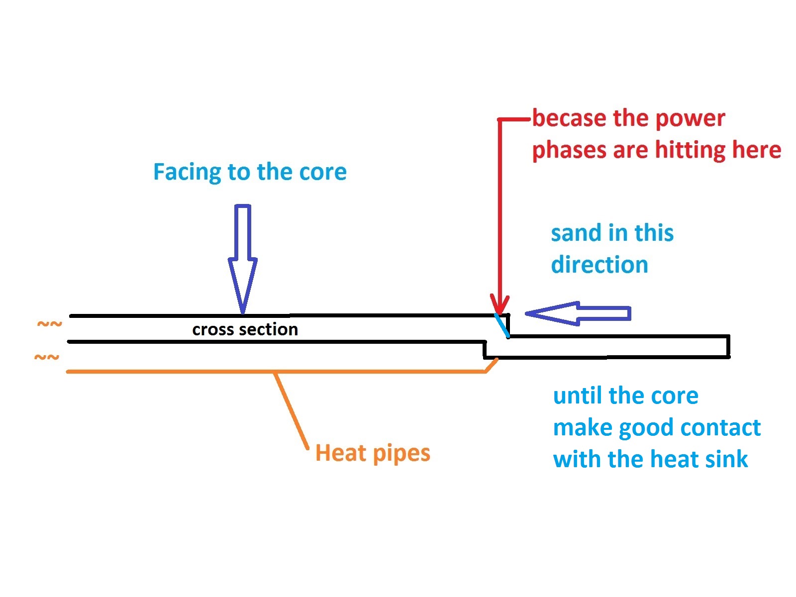
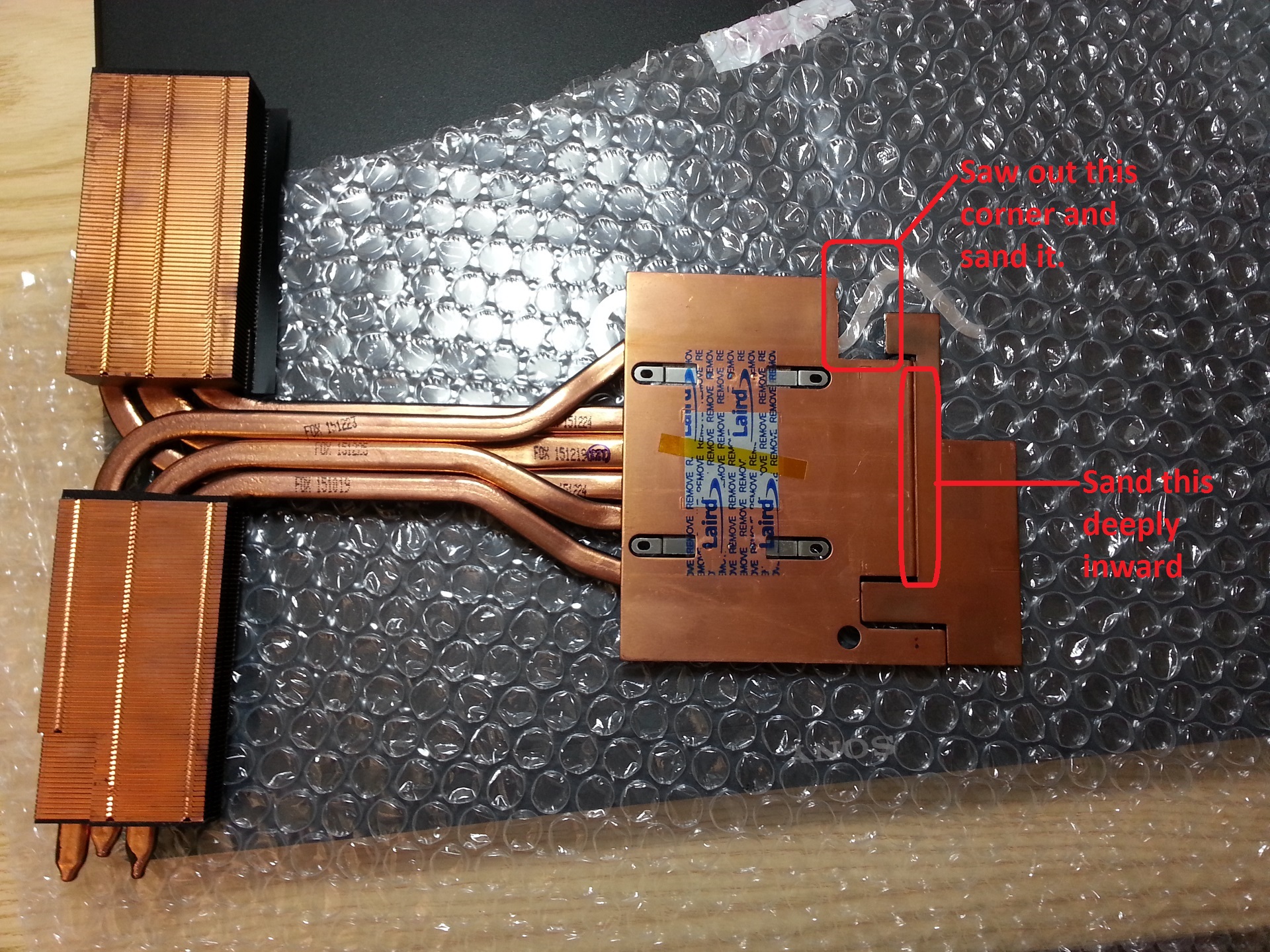
About modding the 980DT heat sink, please take a look of the picture below (corner was cut out already). You can compare with yours and see the changes. If you align the MSI 1070 with the 980DT heat sink, you will find those power phases popping the copper panel and preventing the GPU core from making good contact with the heat sink. Especially the individual one in the corner. I used a hacksaw to cut out the corner, and used the 400 sandpaper to deep-sand the places that I circled, following with refined sanding using 800-grit paper and 2000 grit for polishing. This required a lot of works, I would say adding extra (maybe 3) heat pipes on top of the 980M heat sink would be much easier if you don't want the trouble. About the vbios of the 1070, I will recommend to wait for what @prema might come up later or a modded nvflash. Because at this moment, as I know, any modification of the pascal vbios cannot bypass the nvflash and requires a programmer to program it. This involves extra spending in a programmer and higher risk of bricking a card easily. I can't provide the vbios because it's not my property. I found it in a chinese forum; if you search "vBIOS硬刷 Pascal GTX1060/70/80" in google, maybe you will find the original thread. The below post by Dreamonic is a reference of editing the pascal vbios using hex-editor, I tried to mod it by myself and resulted in black screen on boot, not sure what is the cause. http://www.techinferno.com/haven/threads/94/

-
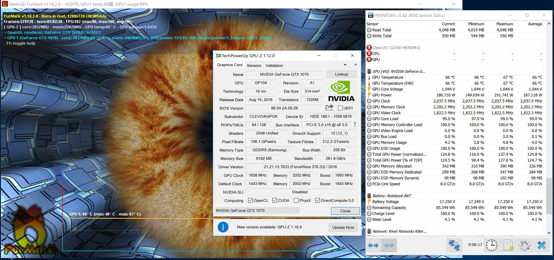
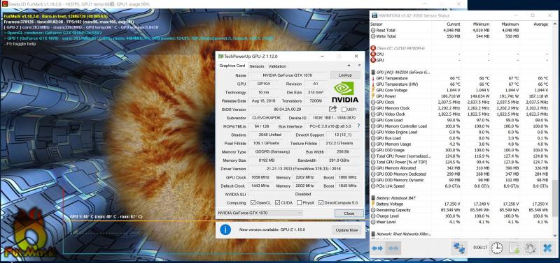
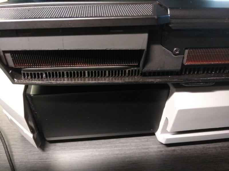
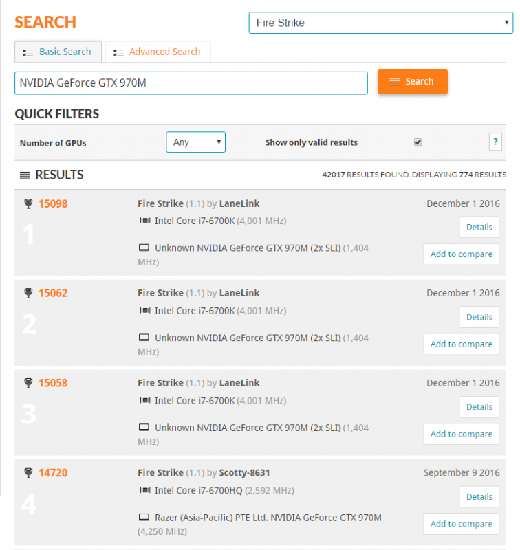
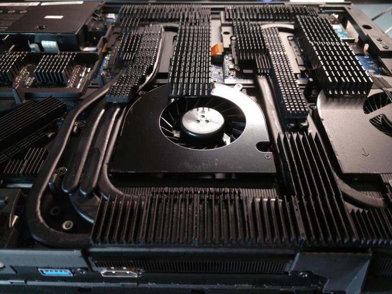
Though my pair of 970Ms is still doing fine in FHD or QHD gaming, but some of the games that I like do not support SLI, such as Gears of War 4, Horizon 3, Quantum Break, etc. This annoyed me sometimes, and happened that I had a chance to be in China for 2 weeks. So well, just did some treasure hunt, and found a MSI 1070 in good price. Here begins with some benchmarks: Immediately unlocked the card to 200W TDP, core +215 MHz, mem +655 MHz: Fire Strike, over 21K GPU score: http://www.3dmark.com/fs/11324399 Fire Strike Extreme, over 10K GPU score: http://www.3dmark.com/fs/11324446 Time Spy: 6.8K GPU score: http://www.3dmark.com/spy/1009997 3DMark 11 Extreme, over 9K GPU score: http://www.3dmark.com/3dm11/11882793 Behind the scene: Programmed the vBIOS chip to 200W TDP using the SP16-B programmer, the chipset model is MXIC 25U8033E: Modded the 980DT heat sink for standard card, required patiently sawing a corner and sanding work. Added 7 heat pipes for extra cooling: Re-modded the CPU heat sink for better looking (got some phobia of small dense heat sinks), added 7 heat pipes also: Loading temperature of 200W TDP in Furmark with 1280x720 (4xMSAA) after one hour: Personally I think setting of 720p + 4xMSAA can very well represent general gaming load, 0xMSAA or 2xMSAA consumes too much heat and non realistic, not recommended. Cost (got everything from taobao.com): new MSI 1070: $660; new 980DT heat sink: $65; Heat pipe: $2 ~ 3 each depends on length; SP16-B programmer: $70; Also got a new B173ZAN01.0 for only $65 (including added $5 for picking a perfect screen); 40 pins EDP cable $35.


-
Thanks. I managed to close the bottom cover and tighten the screws on four corners. For the screws in the center and middle rear locations, I had to change to longer screws to reach it. Bottom doesn't look even/flat as expected, but the sides and the back look fine. Since now I barely move my laptop, so I guess this is acceptable to me.

-
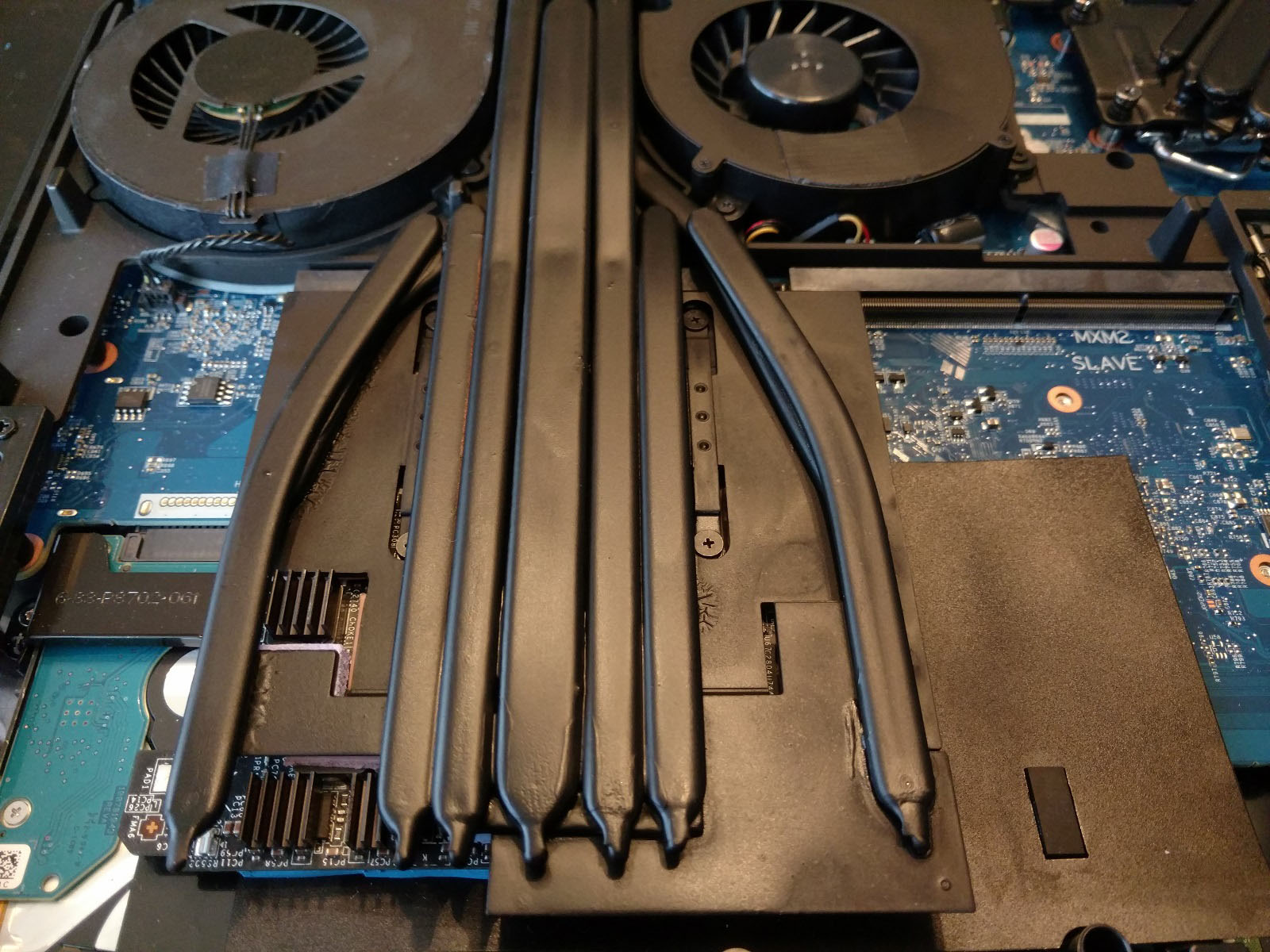
Keep playing with my obsolete 970Ms. Core: 1404 MHz; Mem: 6500 MHz Fire Strike GPU score over 20K: http://www.3dmark.com/fs/10941230 3DMark 11 GPU score about 27K: http://www.3dmark.com/3dm11/11785344 Beaten the Razer BGA + Titan XP eGPU, got my 970Ms throne back: Painted my heatsinks all in black color, it looks better now. Looks like Lego, lol.
-
Just spotted the full standard mxm board GTX 1070 from a chinese forum, seems like it's from ZOTAC mini pc EN 1070. From the color and design of the board, maybe it's made by MSI? http://tieba.baidu.com/p/4848930195 Edited: Seems like the post in the link was deleted or hidden now, this is suspicious... ZOTAC EN 1070: https://www.zotac.com/us/product/mini_pcs/magnus-en1070
-
Thanks. I have been wanted to set it to T1/CR1 for so long, but the BIOS/NVRAM won't save my change after reboot. I also tried to set it through Khenglish's UEFI method, but after reboot the value was reset back to T2. Not sure is it because of the mother board limitation or my memory sticks. Using UEFI variables, I could set voltage over 1.20v, but I still can't boot my sticks to 3100 or 3192 MHz with 1.30 or 1.35v. Last time I used CR1 was in my sold gt72s barebone, I could clock the 4x8G 2133 (normal green kingston) to 2600@14-14-14-28-CR1.