Leaderboard


Popular Content
Showing content with the highest reputation on 09/10/15 in all areas
-
Hardware: Macbook 11,3/2014/15" 750m Gigabyte GeForce GTX 970 OC Mini-ITX (350.12 WHQL) EVGA 400w PSU AKiTiO Thunder2 Windows 8.1 UEFI OSX 10.11 GM (15A282a) [thanks goalque!] Molex > Barrel cable 24pin PSU power switch Install eGPU on El Cap GM 15A282a: Disable SIP Download automate-eGPU connect eGPU cd to automate-eGPU and use -url to download and install WebDriver-346.03.01b07 in terminal: sudo ./automate-eGPU.sh -url http://us.download.nvidia.com/tYGrxreBnE8b89jZ0VysebeSwZJehZTa/WebDriver-346.03.01b07.pkg Restart Optional: Install CUDA 7.0.64 drivers Benchmarks: over 9000. (Link) Overclocking: I used nvflash/maxwell bios tweaker to raise max temp target/power limit. The power limit is raised to a max of 175% but I really wouldn't recommend running it at that level. Download nvflash + maxwell bios tweaker + 175% bios (GV-N970IXOC-4GD only!!!) MSI Afterburner settings: Surprisingly, the little card is very stable at these settings. Raising the memory clock to 8GHz introduces some artifacts however. 100% vs 140% Powerlimit (FurMark) Big thanks to Tech Inferno Fan, goalque and the rest of the Tech|Inferno community!3 points
-
I'm always happy to contribute My cpu is a 3630QM and I can confirm that once I add JEDEC timmings @ 1866, all I have to do is shutdown and start again and the memory automatically runs at 1866. A simple Windows 8.1 restart doesn't change the Ram settings. I was unable to get the laptop to boot with any of the Ram modules at 2133 (tested 4 different modules). All of them were 1,50v and manufactured before 2014. The 8GB modules are from 2012. Maybe that's why I can't get more than 1866 @ dual or single channel? Or its my 3630QMs memory controller? This was tested using bios A16. Here is a picture of the weak Ram module. @sagemaru The UEFI variables stick until you remove both the laptops battery and CMOS battery. Please check my post at the top of the previous page for more details about that.2 points
-
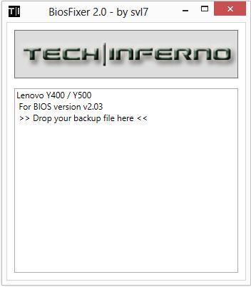
This is continuation of this thread (http://forum.techinferno.com/lenovo-ibm/2690-lenovo-y500-unlocked-bios.html) with all the necessary information in the first post in order to make it easier to find all the stuff. Lenovo Y400 / Y500 - 'unlocked' BIOS / wwan-wlan whitelist removal + modified VBIOS for higher overclocking The Lenovo Y500 comes with a pretty locked down BIOS, and in addition to this with a whitelist which prevents the user from getting 3rd-party wwan/wlan cards to work properly. The modified BIOS versions here will take care of this. Keep in mind that not necessarily all options available in the modified bios will work. Some might not do anything at all, others could possibly leave your system in a state which will prevent it from booting. Use care when changing stuff in the modified bios, don't touch things you're not familiar with. Use all the mods and software posted here on your own risk. Read the instructions carefully. NOTE: This will only flash the bios region. It won't reset the nvars set in the bios. *************** ONLY FLASH A MOD OF THE SAME VERSION AS YOUR CURRENT BIOS VERSION!!! If you're on 2.02 or 2.03 you can safely use the 2.04 update, *************** Attached you'll find modified versions of the Y400 / Y500 BIOS v1.03 and v1.05. Removed as they're outdated. Better updated to v2.02. The bios contains your Windows 8 license, therefore you can't just flash any file, else you'll have issue with your Windows activation. Furthermore the serial numbers, service tags etc. are stored there as well. You don't want to loose them. I wrote a little program that will take care of this issue and personalize the modified bios for you, so that you won't end up with an invalid Windows or no service tags. *************** Preparation to get to BIOS v2.02 (coming from any earlier version): Generally it's a good idea to keep the BIOS up to date. We're luck to have an official BIOS update to v2.02 apparently thanks to a leak on the net. (Lenovo is really bad when it comes to providing firmware updates and fixing issues). The leaked version must be genuine, else it wouldn't flash by using the regular method. If you want to update your system to v2.02 then grab the update here, extract it and flash the bios by executing the included InsydeFlash utility. Once the update is completed you can continue with the instructions below to get a modified version on your system. *************** Instructions for flashing a modified version: As a reminder - the modified BIOS needs to be the same version as you have on your system (2.02 to 2.04 is ok). Prepare an USB stick which can boot DOS. If you don't know how to do this, follow this short guide: Download the flash tool, for flashing you'll need the DOS version, but for creating the backup of your current BIOS the Win64 version will do as well, and it is faster. Get the prr tool as well. Grab the modified BIOS you want to flash, it comes as a tool which will patch the bios for you. Make sure you grab the version that corresponds with your BIOS version. Create a backup of your current BIOS using the flash tool you downloaded (first step) by runing the included backup.bat, or by using the Win or Dos version flash tool with this command: If the .bat doesn't work then open an administrator command prompt in your working directory and run the .bat per command line or type the command written above. In case you get an 'error 104' replace the parts file with the one that can be found in the 'error 104 fix' attachment at the end of the post. And if you still have issues after doing all of the steps above then please leave a reply in the thread and describe your problem. Open the downloaded tool and execute it. Drag and drop your BIOS backup file on it, it will create the mod for you. It will look like this: Put the modified BIOS, the prr.exe tool and the fpt.exe (along with the fparts.txt file) on the root of your prepared DOS bootable USB drive, restart your system and boot from that drive. Execute the prr.exe, if you don't get an error message continue by pressing enter. Then flash the bios by using this command (filename.bin obviously needs to be replaced with the name of the file you want to flash). If you can't remember the name of your file, use the command dir to display all the files on your drive. Flash with this: fpt.exe -f filename.bin -bios NOTE: The name of the BIOS file mustn't exceed eight characters (not counting the extension)! That's a DOS limit, so make sure the name of your file isn't too long. Wait until the process is done. After flashing it will verify the data, in case there's something wrong with the flashed data it will tell you. In that case don't reboot, just flash again. *************** Flashing the ultra bay 650m - only for SLI users with BIOS v2.02: The modified BIOS v2.02 also contains a vbios which will allow you to overclock your 650m past the 135MHz limit. As the ultra bay GPU has it's own vbios module you need to flash it separately. You'll need an USB drive which can boot DOS (just as the one you used for flashing the BIOS). *************** It might look a bit complicated at first, but that's the easiest way I could think of. Let me know if anything is unclear. >> Here's the 'buy me a beer' link in case you like this << Use at your own risk, you are responsible for your system and the changes you make on it. My programs come with absolutely no warranty to the extent permitted by applicable law. Grab file archive here:
 1 point
 -
Instructions for flashing the VBIOS of a NVIDIA video card: You'll need: A VBIOS file you want to flash The latest version of NVflash, a DOS utility to flash the VBIOS of Nvidia cards. A USB drive, formatted to boot DOS, in order to use NVflash How to create a bootable USB flash drive: The flashing procedure: Put the NVflash files to the root of your prepared (DOS bootable) USB drive. Do the same with the Vbios you want to flash. NOTE: DOS has a limit of 8 characters per file name (not counting the extension). So make sure to rename your files appropriately before putting them on the USB drive. Make sure the USB drive is plugged into a port which is active at boot, reboot the system and go to the boot manager. Choose to boot from your prepared USB drive. As soon as you see the command line you're ready to go, write dir and hit enter to display all the files on the USB drive. Display all Nvidia adapters in the system: nvflash -a or alternatively the longer version of the command: nvflash --list This command will return you a list with all Nvidia adapters present in your system. Here's an example output of this command run on my M15x with a 680m in it: NVIDIA Firmware Update Utility (Version 5.117) NVIDIA display adapters present in system: <0> N13E-GTX (10DE,11A0,1028,02A2) H:--:NRM B:02,PCI,D:00,F:00 The number in the <> brackets is the index of the corresponding device. SLI users will have more than one entry and flash each card separately. Backup your current VBIOS: Never forget to keep a backup of your original VBIOS before you flash anything non-stock. Use this command to save a copy of the firmware to your USB drive: nvflash -b filename.rom or with nvflash --save filename.rom Flash the VBIOS to your card(s): For a single card it's really straight forward, you don't need to worry about the adapter indices. Just use this command: nvflash -6 vbiosname.rom -6 will allow you to override mismatches of the PCI subsystem ID. In case of a mismatch you'll need to confirm the flash with 'y'. NOTE: Users with a non-US keyboard might need to press 'z' or similar, because the 'y' isn't at the same location for all keyboard layouts. SLI users will need to flash each card separately. The concept stays the same, but you will need to use the corresponding adapter index to flash a card. How to figure out the adapter nr. is described above. Flashing goes like this: nvflash -i[index] -6 vbios.rom [index] represents a number, namely the index you found with the 'nvflash -a' command. So a command example to flash a card which has index 0 is: 'nvflash -i0 -6 vbios.rom' When the flashing starts, just wait until it says that it's done. Then reboot with Ctrl+Alt+Del and remove your USB drive. Pro tip: Let me know if I missed anything important or if you have questions.1 point
-
Over at NBR in the "Pidge from nVidia" thread I posted up a screenshot of my HWiNFO64 during a sidetrack discussion of GTX 880M temperatures. D2 Ultima pointed out that my PCH was quite toasty: "Woah, the PCH was hitting 98 and averaging 95 there. Those things have an upper limit of 100c-105c, you should probably keep an eye on it or maybe try a cooling mod for it?" For those that are wondering... the PCH (Primary Controller Hub) is basically what used to a be known as a Southbridge. This all lead to further derailment of that thread to a short discussion of on PCH temps. My PCH has actually seen 108.5C as of the day before yesterday. That prompted me to tear down my laptop that evening. I started late and worked until 2am. Then I went to bed and finished up the next morning. Ok, enough prep. This is what I did. I had read that the P17xx series were a bit different than the P15x and P37x in terms of what it looks like under the keyboard. The other two models have free access to the PCH. Here is a link to n=1's PCH cooling mod for the P370SM. 5 mniute mod to improving PCH cooling in P370SM Well, it isn't quite so simple with the P17x series. As you can see, there is a big ol' chunk of plastic in the way. I can cut it, but I am not going near the assembled laptop with my dremel. A disassembly is in order to get to this thing. I am OK with that because I see it as a challenge and a chance to learn something (even if it's what not to do). Here is what I thought was an interesting picture. I have the top case all but separated from the bottom case. Getting the keyboard off is pretty easy. Just be careful of the two ribbon connectors. One is for the keyboard and one is for the backlight. The backlight ribbon is a pain in the butt to put back. All of the other ribbon cable connectors slide away from connector to release the ribbon. The backlight connector flips up. I didn't know that and I slide it away and the lock popped off. After some fiddling with it I dug through the service manual and the light went on. It's a tiny little bugger, but I got it back into place and everything still works. In this picture, the laptop is open and standing on the right side. The screen is on the far right and the bottom casing is on the far left. The top case is in the middle. Here you can barely see the PCH nestled under that nice, insulating plastic. No real hope of getting a breath of fresh air. In the second picture I have disassembled the laptop enough to get a better peek at the little hottie. My goal is to remove the top case so I can cut a hole in it and stack up thermal pads so they touch the bottom of the keyboard, which is a huge aluminum plate. This will make a nice heatsink for the PCH. This is the same thing that n=1 has done, only with less hassle than us P17x owners. Here the top case has been removed and you can now clearly see the PCH. I just eyeballed the location and marked it with a sharpie so I would have a guide before I head out to the garage for cutting. In a few minutes it's all done. I used a cutoff wheel at low speed. I cut straight down into the material from the top and then flipped it over and did the same thing from the bottom. Then I just pushed out the square cutout with my thumb. I am not too concerned about appearances with this mod as it won't normally be seen. After I was done cutting I used a wire brush at low speed to clean up the rough edges. I put the top case back on and find that my eyeballing wasn't too bad. Looks like I hit the mark pretty close. w00t! Now the only problem I have is I don't know how much stackup I need for my thermal pads. I used a 1/4 sheet of 1mm, 11.0 W/mK thermal pad from FrozenCPU.com which i cut with ordinary scissors. But, how tall to stack it? The answer is: modeling clay to the rescue. I just formed some modeling clay and stuck it on top of the PCH. Then I test fitted my keyboard, smushing the modeling clay. After that I removed the keyboard and measured the height of the smooshed modeling clay with my dial calipers. I measured .164" which is a bit more than 4mm. I cut and stacked 5 layers of 1mm thermal pad to make sure I had good contact. Then just put everything back together and played some games. The result was pretty good. The most I have seen is 85C on the PCH. The down side is the keyboard gets quite a bit warmer. I think the trade off is worth it. I was able to drop the max PCH temperature by 20c with this mod. BONUS: For those that are wondering, all three antennas are routed up to the screen bezel even if your configuration only uses two antennas. This is nice to know. If you think about it, it's a lot easier for Clevo to do this by default. The parts aren't expensive and it's one less thing to track if they all get it.1 point
-
wormholev2 wrote at i5 NUC and GTX980 - [H]ard|Forum1 point
-
Just to confirm- This is working on the new El Cap GM (15A282a) with WebDriver-346.03.01b07. See my post1 point
-
Hey guys. Sorry to intervene. I've recently upgraded my bios to A16 and I can still use UEFI variables to enable Raid0, change TOLUD and select XMP Ram profiles. eGPU still works without issues. Tested in Windows 8.1 x64 using EC.1 point