Leaderboard


Popular Content
Showing content with the highest reputation on 08/20/11 in all areas
-
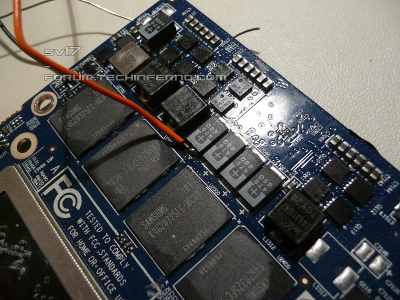
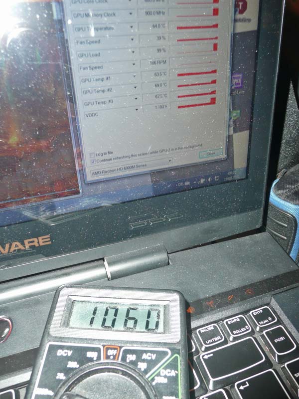
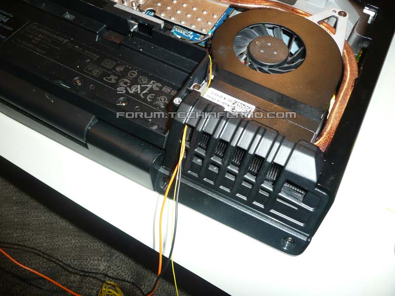
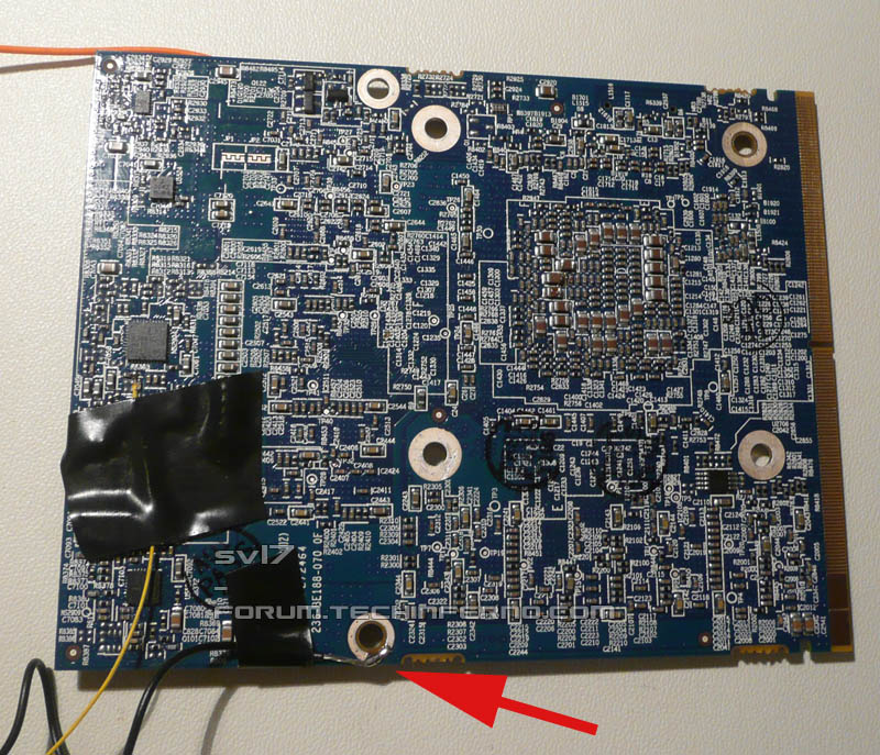
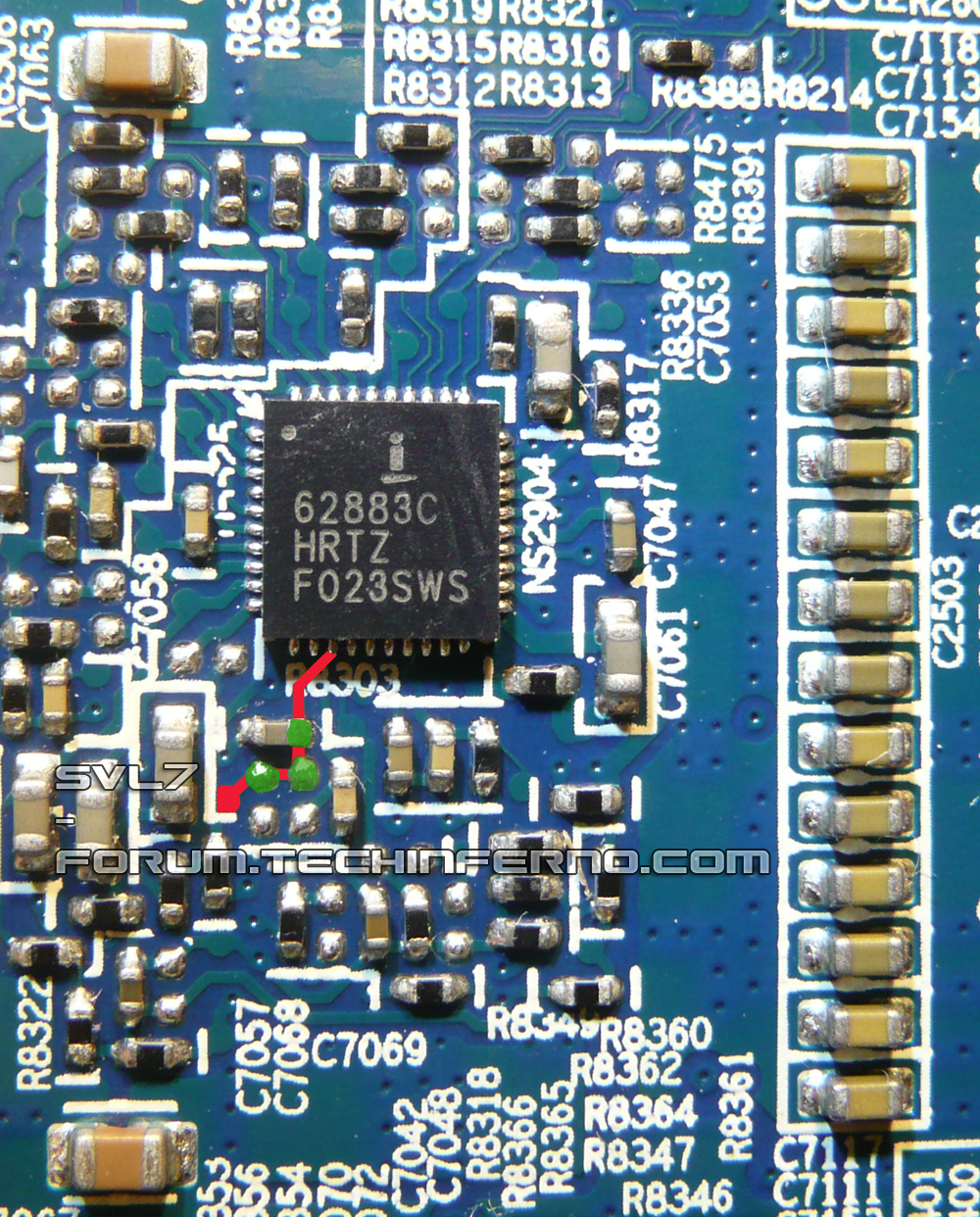
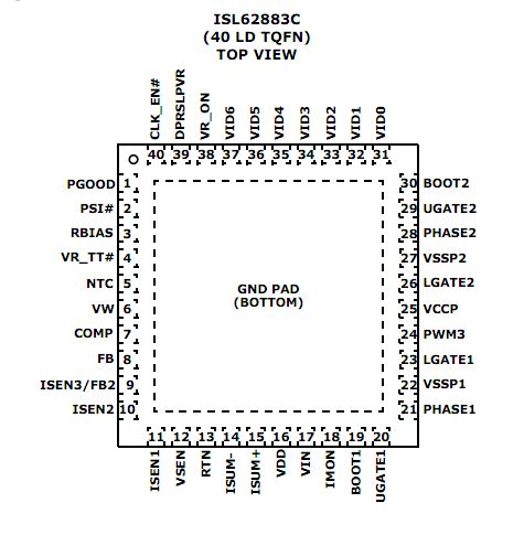
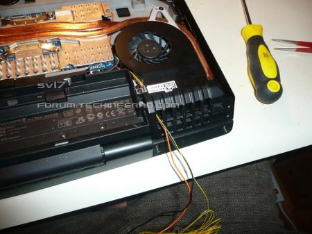
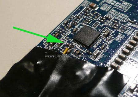
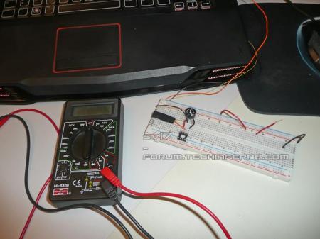
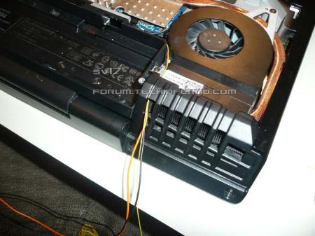
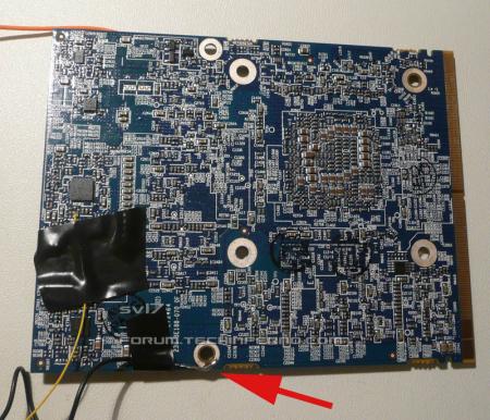
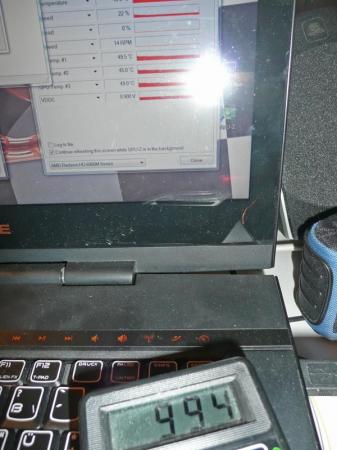
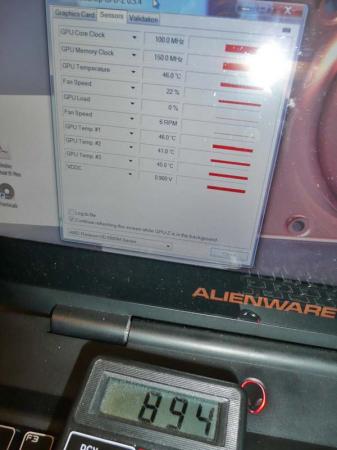
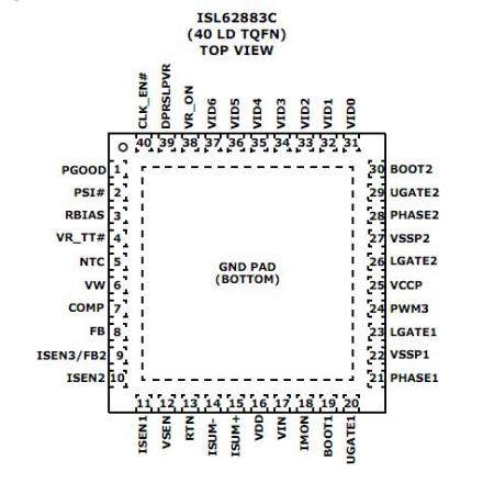
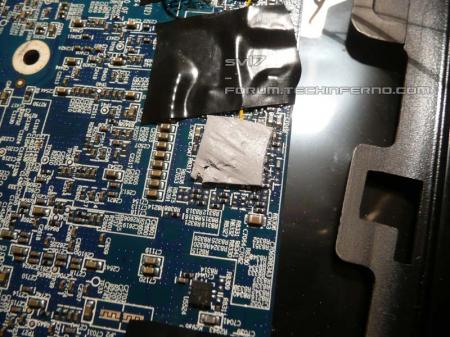
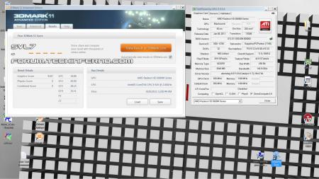
The AMD 6970m is an amazing card, great price performance ratio and really powerful. Only drawback I see is that there's no way to increase the voltage of the card through the VBIOS. This limits the maximum possible overclock and minimizes the benching capabilities of this card. To solve this I decided to do some modifications directly at the hardware which allow me to increase and also monitor the core voltage of the GPU How does it work? The core voltage of the GPU gets controlled by a PWM regulator made by intersil, the ISL62883C. It's a small 40 pin SMD chip, here you can see the pin configuration of it: The exact purpose of each pin is described in the datasheet which you can find at the end of this post as attachement. I won't go into details about how the chip exactly works, all that is needed for the voltage mod is Pin 12 (VSEN). This is the voltage sensing pin of the PWM controller, it monitors the current GPU voltage. As soon as the voltage drops below a certain level (e.g. because there's suddenly more load on the GPU), the chip will automatically give an additional PWM signal to bring the voltage back to the set level. So if the voltage at Pin 12 is too low, the voltage gets raised. This means if you trick the chip into thinking the current core voltage is too low (even though it isn't), it will automatically raise it (and thus overvolt the GPU). This can be achieved by slightly dropping the voltage at VSEN. The resistance between Pin 12 and ground is about 14Ω, putting a variable resistor between ground Pin 12 will allow lowering the resistance between ground an VSEN and thus lowering the voltage at VSEN. The resulting resistance is R1*R2/(R1+R2), R1=14Ω, R2 = potentiometer used for the mod. A 500Ω potentiometer will do the job, I use a 1kΩ which is fine as well. So all that's needed is: - a potentiometer between VSEN and Ground - a measuring point to monitor the GPU core voltage Here you can see the conducting path that leads away from Pin 12 (red), possible solder spots for the mod are marked with green. The parts are pretty tiny, you'll need a steady hand and a fine solder tip if you want to do this. It can be done without a magnifying glass, but it's good to have one for checking the solder joint afterwards. On the left picture you can see the cable which leads to one end of the potentiometer soldered to the card. Could be better, but it works. The other end of the potentiometer needs to be connected with ground. Since ground connection of the PWM chip isn't accessible (it's on the bottom of it) I had to look for a different possibility. I decided to go for an easy to solder spot, see the picture. This works fine, it has a big contact surface and soldering on a cable there is peanuts. Such a voltmod requires a possibility to properly monitor the GPU core voltage. You can't just adjust it without knowing how much it gets changed (unless you want to burn your card). Since this isn't a desktop system it's not possible to simply do some measuring with a multimeter while the system is running, you need to solder on a cable to a measuring point for the core voltage. The easiest possibility is to use one of the big electrolytic capacitors on the top of the card (the positive end obviously). Other possibilities are some of the ceramic capacitors on the other side of the die (which would probably be slightly more accurate). I tried this, but it's a PITA to solder there and I ended up going the easy way. For ground reference you can simply use the ground cable which is connected with the variable resistor. I also padded the VR with a high-end thermal pad. It'll run warmer than usual with the increased voltage. Hopefully it helps a bit. On the other pictures you can see the cables leading from the GPU leaving the system. Black is ground, yellow leads to VSEN and orange is the reference for the GPU core voltage. The picture on the very right shows my voltage control center The potentiometer mounted in a breadboard, this allows to quickly remove the mod. Here some quick tests. The first picture shows the system with the GPU idling, my multimeter reads 894mV and the VBIOS value is 0.9V (see GPU-Z)... perfect! Middle: System at 100% GPU load (furmark), multimeter reading 1060mV, VBIOS value is 1.1V. Right: GPU idle, I increased the voltage to 1V, card is still set to 0.9V (see GPU-Z) So... yes, it works, but... there's a huge problem. When I did some very quick tests with furmark, the voltage gets automatically set back... I raised it further and further, until it didn't get set back anymore and I had a voltage of 1.2V... but the core clock dropped to 400 MHz. I guess there's something limiting the maximum current, an overcurrent protection. Though what bothers me as well, was that according to GPU-Z, the VBIOS sets the voltage back to 1.0V when I raise it above a certain limit, so the VBIOS might be involved in this as well... I'm not sure. More testing will come as soon as possible, I'll also try to force the clocks in the VBIOS. I really hope to get this working. If you have any ideas, please let me know. Also if something needs a more thorough explanation, just aks. __________________________________________________- EDIT: This definitely works!! Just did some 3dM11 tests at 915MHz and more. I though I solved the downclocking issue, but it's still there, randomly. It's probably caused by software issues (driver, ... ). Since I was really annoyed by this I decided to simply mod the VBIOS and set the 3d clocks and the battery clocks to 915MHz (and later more). This worked, the clocks got forced to this level, so this indicates that it isn't caused by the card, but by software issues. Here's a 3dM11 test at 915MHz core, 1100MHz Memory: You may realize that it's not really a highscore for the M15x. I had to leave the CPU at stock settings, otherwise I run into serious power issues. Take a look at the graphics score, that's more interesting. As comparison, The Rev got 3965 GPU score on his best (submitted) 3dM11 test with the 6970m. This one is at 935MHz, only the GPU tests: I think there's even more headroom for the clocks, I upped the voltage to 1.25V, this should allow to get the clocks even slightly further, but I think I'll get limited by the VRAM at a certain point. Maybe I'll look for a voltmod for the VRAMs as well, but considering that there's already a power issue with this mod, it probably won't be of much use in the M15x. Run out of time, sorry, I actually wanted to do some more testing, but the term started again today and I'll be pretty busy from now on. Also I had some other software issues, I guess my bench partition needs some work... reinstallation and fine tuning. This was a very quick edit, just ask questions if something's unclear! ISL62883C - 6970m.pdf


 1 point
 -
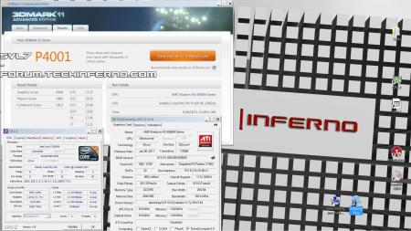
what you guys think of this, lolz
 1 point
 -
I have some 580m VBIOS files from the Dell 580m here... one from the r3 and one from the M18x, found them online, here you go: Dell 580m package.zip1 point
-
Even though I am in bad mood, this made me laugh hard http://youtu.be/xJJBrxEo2Wk1 point