timohour
-
Posts
295 -
Joined
-
Last visited
-
Days Won
12
Content Type
Profiles
Forums
Downloads
Everything posted by timohour
-
 Dell USB 3.0 E-Modular Bay. Schematics show that port 4 goes to the modular bay. Since it is a shared product for Sandy Bridge (Latitude E6x20 laptops) and Ivy Bridge (Latitude E6x30) I assumed that the Modular Bay uses some kind of PCIe-->USB 3.0 card (There are NEC USB 3.0 drivers on the E6420 drivers page, Sandy Bridge did not offer native USB 3.0). Here is a shop that guarantees that it works with E6x20 and E6x30, which means that pcie port 4 is probably wired. Correct. Seems like it. Everything you say is as I see it on the picture. I will test on my E6430 tomorrow and get back. Just make sure that on your riser RX+- goes to pcie lane 1 RX+- (pins A21-22), TX+- goes to pcie lane1 TX+-(pins B19-20) as on the picture in the spoiler. I connected them the other way the first time I tried. If you tried and it still doesn't work, there is maybe something changed since the revision of the schematics we have. Have you confirmed that port3 is set @ x2 mode? If you own Setup 1.x or any other program that can check, make sure that port 1 and port 3 are set @ x2 mode (port 2 WiFi would be disabled).
 -
Lets enable overclocking on all 6 and 7 series laptops
timohour replied to Khenglish's topic in General Notebook Discussions
Thanks for the heads up. For anyone interested E6430_OC Thanks again. I have already done that here. We are now trying to enable port 4 (e-module) to create an x4 link here. Any help would be much appreciated. -
It is not that easy to test x1 on the module bay. You have to solder at least REFCLKs WAKE# and PERST# along with RXs TXs. I assume from what you write that you connected pins 18-23 from port JSATA2 on schematic. If I am right on this one, is there any possibility that you have connected the wrong pins or in the wrong sequence? From my observation I think that those pins are near with those of the SATA power, correct? Maybe they are the other way around? Is it possible that youcan get a picture of the area so we can have an idea how it is beneath the sata connector? Thanks I don't think that we need any of the two MOD_ * They both seem to be related with the USB 3.0 function of the E-module II.
-
If you did flash your descriptor as I mentioned it will be permanently writable. You have to do it though after you apply the pinmod and before you reboot. You didn't have to wreck your ODD PORT. As I noted on this post a mini pcie card fits in there (as long as thickness and pin distance is concerned) and you have to cut some of the PM3 to make it fit into the ODD slot and thinsulate those pins that are not used! Anyway, I hope that it works that way too. Waiting for your results!! If you are interested since you unlocked your descriptor you can know unlock your ME firmware so it will allow BCLK OC. Check this thread out. Unlocking your ME firmware will allow you to OC your CPU up to 5%. I OCed an my i7-3630QM from 3.4GHz to 3.56GHz by setting BCLK @ 104,9. I will be posting more about this mod too.
-
Lets enable overclocking on all 6 and 7 series laptops
timohour replied to Khenglish's topic in General Notebook Discussions
Works for Dell Latitude E6430! How to unlock your flash Descriptor on a Dell Latitude E6430 (dGPU/iGPU) i7-3630QM @ 3.56GHz Many Thanks @Khenglish for helping me with the ME firmware edit. I wouldn't have succeeded without his help Just in case someone happens to have the same problem. I did manage to enable the slider but it wouldn't go over 100MHz. Khenglish explained to me that I hadn't change the clock range definition record and he kindly provided me a correct image of my BIOS. Since this is his work I am not sure I can provide it without his consent. -
Help request for adding PCIex16 port on laptop (soldering)
timohour replied to AGmR's topic in DIY e-GPU Projects
It seems like your laptop comes with a dGPU (7670M). Can you enable/disable it in your BIOS? -
Great Work there! It seems like the iGPU model have the 92HD90B2X5 chip on the other side of the motherboard. Added it here for future reference. Is it possible to make the pinmod without taking apart the laptop? Thanks for your insight
-
For my setup I used a mini pcie to pcie connector (this one) and a PCI-E 16X to 1X Adapter USB 3.0 (like one of these). I realised later that the mini pcie to pcie connector was only PCI-E 1.1 capable which was the reason why it wouldn't work with the Nvidia card @ 2.0. It worked with my R9-280x card though. I tested the PCI-E 16X to 1X Adapter USB 3.0 with my PE3A and with my Desktop and it wouldn't have a problem to provide a stable connection @ x1 2.0. Unfortunately, my PE3A is now dead (for no reason) and I am probably getting a PE4C for an x2 2.0. Make sure you make no mistake with this one. The ODD port is a dual port. On the one side (of the 7+6 pin slimline SATA port you mention) is the SATA and power connection and on the other side is the pci-e connection for the e-module II. As I noted on this post a mini pcie card fits in there (as long as thickness and pin distance is concerned) and you have to cut some of the PM3 to make it fit into the ODD slot and thinsulate those pins that are not used. I started the work to confirm the theory but my PE3A stopped working and I don't have the right gear to test it. As far as alternative cables are concerned I can say that a good quality USB 3.0 cable would suffice for 2.0 signals (tested on Desktop and Laptop with a cheap x1 to x16 BTC) and I don't find a reason why SATA 3 (6Gbps) or SATA express cables won't work (2 for the first connection and 1 for every other). If you use sata cables you can even use a adapter like this for the x2 connection the Sata signal on the msata pinout is on the same pins as the pcie (PET and PER) signals on the mini pcie pinout. EDIT: cat6 can handle 10Gbps for 55m and cat6a & cat7 cable can handle 10Gbps for 100m. Maybe it is possible to use flat twisted pairs for cable... I am still undecided on which adapter I choose but I am probably getting the PE4C and solder the rest to test x4 2.0. I am not planning to use x4 2.0 on a daily basis. x2 2.0 external solution using EC port 3 and e-module port 4 would be the ideal solution for me.
- 807 replies
-
- 1
-

-
- dell latitude e6430
- e6430
- (and 2 more)
-
As far as I understand with a PM4N adapter you would probably won't get reliable 2.0 signal. I am not sure though if someone have tested connecting a PE4C with PM4N. If you are interested in a smaller cable I see here that they also ship the PM050C V1.0 which is 50cm, just 20cm bigger.
-
Hello there @TheClassicalCat If you are interested in running x2 2.0 you should probably look for PE4C with 2 mini pcie using ports (port 1 and 2) or you can mod a PM3N adapter by moding, I mean you should cut the PM3N connector to fit into the ODD/Emodule connector and use tape to isolate all the pins, apart from pins 21, 23, 25, 27, 29, 31, 33, 35 which carry the PET and PER signals to connect on the module bay port 4 and use EC port 3 and port 4. I haven't done it yet but visually it fits and according to schematics it appears that the pins are in the correct order. I will upload pictures here of how a modded PM3N should be when I find the time to finish the mod. if you are interested on a x4, as nando said there is no tested adapter that can handle perfect x4 2.0 signal. You can try the PE4H 2.4a adapter but you should mod the PM3N again for port 4 as described. Keep in mind that using port 4 Emodule II is not something that I have already tested but I only assume it will work in theory according to schematics. - - - Updated - - - all you can do is wait... If you are willing to make an internal solution x2 2.0 (using wwan port 1 and wlan port 2) you should buy an extra PM100c or PM50c cable. If you are looking for a full external solution (using port 3 & 4 (EC & EModule II) you can try to use the PE4C-EC100C along with and extra PM100c or PM50c cable. *check above* You don't need to change your TOLUD if you are going to use Setup 1.30. You need it only if you are going to install UEFI Windows 8.1. I haven't described the precedure here yet but it is easy. Check the post here It should be that easy.
- 807 replies
-
- 1
-
-
- dell latitude e6430
- e6430
- (and 2 more)
-
Hello there @TheClassicalCat If you are interested in running x2 2.0 you should probably look for PE4C with 2 mini pcie using ports (port 1 and 2) or you can mod a PM3N adapter by moding, I mean you should cut the PM3N connector to fit into the ODD/Emodule connector and use tape to isolate all the pins, apart from pins 21, 23, 25, 27, 29, 31, 33, 35 which carry the PET and PER signals to connect on the module bay port 4 and use EC port 3 and port 4. I haven't done it yet but visually it fits and according to schematics it appears that the pins are in the correct order. I will upload pictures @ 6430 system mods when I find the time to finish the mod. if you are interested on a x4, as nando said there is no tested adapter that can handle perfect x4 2.0 signal. You can try the PE4H 2.4a adapter but you should mod the PM3N again for port 4 as described. Keep in mind that using port 4 Emodule II is not something that I have already tested but I only assume it will work in theory according to schematics.
-
You can use Thaiphoon Burner (16$ personal edition). I think that Thaiphoon Burner 6.3 (latest free edition) won't work. Make sure you check if your memory is NOT PSW protected before you purchase TB. Impressive work. I never tried that. My E6430 is the one with the dGPU but I think I will try that. Very interesting! I never thought of using my NVS5200 for gaming. I am afraid that these chips are not of good quality. Inform us of your findings... We can make it an 6x30 thread linking all of your works so far on E6530. Let me know if this is OK with you.
-
I don't have a 2nd dimm right now. I am going to test dual channel as soon as I get one.EDIT: Performance Gain using faster RAM on a Dell Latitude E6430 AIDA64 SINGLE CHANNEL DUAL CHANNEL SPD 1600 CL11 STOCK 1866 CL10 XMP 2133 CL11 XMP 1333 CL9 STOCK 1600 CL9 XMP 1866 CL10 XMP 2133 CL12 PnP 2230 CL12 OC PnP AIDA READ MB/s 11915 13905 15672 19137 23111 26513 28310 30721 AIDA WRITE MB/s 11928 13388 15715 19075 22702 26513 28275 30699 AIDA COPY MB/s 11160 12322 14713 17479 21103 24158 25535 28106 GAIN up to 13% from 1600 up to 30% from 1600 up to 20% from 1333 up to 15% from 1600 up to 25% from 1600 up to 35% from 1600 Total gain goes up to 158% from DDR3-1600 Single channel to DDR3-2230 Dual Channel!!!3DMark06 SINGLE CHANNEL DUAL CHANNEL SPD 1600 CL11 STOCK 1866 CL10 XMP 1333 CL9 STOCK 1600 CL9 XMP 1866 CL10 XMP 2133 CL12 PnP 2230 CL12 OC PnP SM2.0 score 1596 1765 1963 2203 2231 2444 2595 HDR/SM3.0 score 2068 2404 2819 2954 3014 3281 3445 3DMark06 score 4941 5707 6595 7078 7191 7815 8232 GAIN up to 16% from 1600 up to 8% from 1333 up to 4% from 1600 up to 11% from 1600 up to 17% from 1600 NOTE: For 2133MHz and 2230MHz I used my i7-3720QM CPU because my i7-3630QM's memory controler couldn't handle the stress. In order to give similar CPU performance I used Throttlestop to set the maximum multiplier to x32 for all cores oposed to the i7-3630QM which runs (x34-1C, x33-2C, x32-4C). What's really amazing is the nearly 65% gain from DDR3-1600 single channel to DDR3-2230 in graphics performance for the HD4000.
- 807 replies
-
- 3
-
-
- dell latitude e6430
- e6430
- (and 2 more)
-
[GUIDE] Dell E6530 CPU TDP/multi unlocking
timohour replied to Khenglish's topic in Dell Latitude, Vostro, and Precision
Thanks a lot for your findings. Just to add that, you can enable XMP Profiles and use them to OC your RAM. Check here. -
Enabling XMP (eXtreme Memory Profiles) on a Dell Latitude E6430 to improve RAM performance EDIT: Seems like you don't need to use XMP Profiles to enable RAM OC.On my E6430 I could use Kingston PnP memory modules which automatically overclocked @ 2133MHz. This means that it would correctly OC every memory that have an 2133 JEDEC profile. This guide remains here for those that own memory with PSW protection that can't be flashed with JEDEC values, only XMP. You can easily run XMP enabled memories @ advertised timings using the UEFI variables. You can read more about how this works @ [GUIDE] Dell E6530 CPU TDP/multi unlocking thread made by Khenglish and Tech Inferno Fan. I just used their work to get a little further. If you carefully read the guide on the thread above then you know how to use the UEFI variables. All you have to do is change settings for UEFI variable DIMM profile: Option: Default DIMM profile, Value: 0x0 {09 0E 02 04 30 00 00 00 00 00 00 00 00 00} Option: Custom profile, Value: 0x1 {09 0E 05 04 00 00 01 00 00 00 00 00 00 00} Option: XMP profile 1, Value: 0x2 {09 0E 03 04 00 00 02 00 00 00 00 00 00 00} Option: XMP profile 2, Value: 0x3 {09 0E 04 04 00 00 03 00 00 00 00 00 00 00} End of Options {29 02} Setting: DIMM profile, Variable: 0x1EE {05 A6 00 04 01 04 20 04 02 00 EE 01 14 10 00 ... 00 00} If you buy XMP memories you can set them to run @ their XMP speeds & timings. But what happens if you don't want to buy new RAM? You can flash XMP Profiles on the SPD EEPROM chip on some RAM. My 4GB SO-DIMM 1.35V Samsung M471B5173CB0-YK0 was unprotected. EDIT: Even locked chips most times (all that I tested) allow you to flash an XMP Profile. They just won't let you flash the JEDEC Profiles. There are two options if you want to flash your RAM: Purchase Thaiphoon Burner (16$ for personal use) Use SPDtool for free if you have an older laptop around with DDR3 that supports it. Luckily, we have 4 Lenovo G550 at work which use GM45 chipset. My first step was to find a working XMP Profile 1.3. Then all I had to do was use the G550 and SPDtool to flash it. Although there are lots of them on Thaiphoon DEMO Database, I only found a Crucial Ballistix 1866J dump that was running 1866MHz @ 1,35V. All I had to do was try. I couldn't make the lenovo G550 to boot with 4GB stick so I just hotplug. After this, took a backup of my memory dump and flashed the dump from B0 to FF (it is were the XMP 1.3 Profiles are stored) All I had to do now was to use setup_var (following Atonus instructions) to enable XMP Profile 1 or 2. AIDA64 COMPARISON Impressive ~15% performance improvement 3DMark06 with HD4000 Impressive ~14% performance improvement I saw an improvement of 15% @ 1866 and 31% @ 2133!!! and and I assume that if I find a XMP Profile to set my RAM @2400 the results will be even better. EDIT:More test including dual channel results here Make sure you use a i5 or i7. With a i3 the RAM will only take the timings but still clock @ 800MHz Many thanks to @Tech Inferno Fan, @Khenglish, @Atonus. Without them, this would never be possible. EDIT 2: Seems like 2400MHz is not possible. Even if you set an XMP Profile higher than 2133 (2400, 2666, 2800) it will downclock to 2133. I can't find a reason why this is happening. Maybe my CPU (i7-3630QM)? I can not even test dual channel @ 2133. The 2GB ADATA chip that I have won't go up to 2133... 2000MHz CL11 seems to be its limit and only single channel....
- 807 replies
-
- 4
-
-
- dell latitude e6430
- e6430
- (and 2 more)
-
EDIT:Guide here on how to unlock your Flash Descryptor and set your port @ x2.2 That's right. Last night I tried to connect my R9-280x @ x2 2.0 with the same homemade adapter and 3Dmark06 run just great. Disregard the low results I run the tests on battery cause I forgot my adapter @ work 3Dmark11 and 13 refuse to run on my system but it must be something that has to do with my windows 8.1 installation cause they won't run with the dGPU either. 3dmark13 error message similar to 3dmark11
- 807 replies
-
- 1
-
-
- dell latitude e6430
- e6430
- (and 2 more)
-
Hiding the 2 male HDMI cables from PM100C V1.0 inside the ODD won't cause any signal degradation. Right?
-
Using an extender would probably degrade the signal's quality. As you can see, bplus tried to eliminate the connections on latest products. They use only one HDMI connection on their products. What we could do is mod a ODD caddy to somehow keep the two HDMI cables in there. I am working on a full external solution right now, so we can keep our laptop permanently closed.
-
Connecting 3 external screens on a Dell Latitude E6430 along with a PR02X docking station Since this is the main computer I use at work I bought a Dell PR02X Docking station along with 130W adapter to connect my peripherals. I chose a USB 2.0 PR02X because it comes with a variety of ports including a serial port and 2 displayports and it is fairly cheap. Since we had two old 19" LGs laying around I ordered 2 Displayport to VGA adapters in order to connect those two... I found out though that those two Displayport connectors (and I suspect the two DVI outputs above them) are directly wired to the NVS5200M. Having in mind that the VGA port is connected on the HD4000 I realised that I could connect a 3rd screen there. I borrowed a screen from the nearby office just to confirm and... I can confirm that E6430 dGPU model along with a 40$ USB 2.0 PR02X can handle a total of 3 VGA external screens or even 2 DVI/DP and 1 VGA screens, one on the VGA port of the HD4000 and two with the Displayport to VGA connector. If the HDMI connector is directly wired to the NVS5200M it is possible that it can even drive a 4th screen through the on laptop HDMI port, but I don't have a dvi/hdmi screen around to test... EDIT: Confirmed HDMI is connected on NVS5200M and the E6430 can probably handle 4 external screens. Using 2DP and 1 VGA on docking station plus 1 HDMI connector on laptop. NVS5200M can only handle up to 2 screens. I don't know if this will work with the iGPU model. It is highly possible that you can connect two DP external screens, since HD4000 can drive 3 screens simultaneously as long as two of them are connected with DP. Schematics sho that the wiring of the docking connector for the iGPU model wires both displayports slots to iGPU Displayport C and D. It will most probably work with 2 DP screens or 2 active DP to VGA adapters. If you are interested for more screens you can use a low cost eGPU running through the EC slot.
- 807 replies
-
- 2
-
-
- dell latitude e6430
- e6430
- (and 2 more)
-
I love macs. I just hate their pricetags... That makes two of us... I had some plans but my latest failure sets me back.
- 807 replies
-
- 1
-
-
- dell latitude e6430
- e6430
- (and 2 more)
-
Yep!!! I used the E6430-A07_IFR I decided to use UEFI Win 8.1 installation (getting ready for Win 10) and that's why I cannot use setup 1.30 on this drive. I booted from an eSATA drive where I have Setup 1.30 installed and that's how I got my screenshot. I maybe try to find the UEFI variable to change it from Gen 2 to gen 1. That's great info. I can connect my 280x and see if it works better. I was afraid to use it at the begining but it should work now. Or maybe try an older pcie card. I know that but as you pointed out it is not the one cable TB solution. You know that my quest was to try use the E-module II port 4 and create an x4 2.0 link (just for testing) and conclude with an x2 2.0 external link using EC port3 and E-module II port 4. Having to take apart my laptop every time I want to connect the eGPU is not an acceptable solution for me. If I don't find a way around it I am maybe going to settle for an unupgradeable Macbook Pro too. But where is the fun in that?
- 807 replies
-
- 1
-
-
- dell latitude e6430
- e6430
- (and 2 more)
-
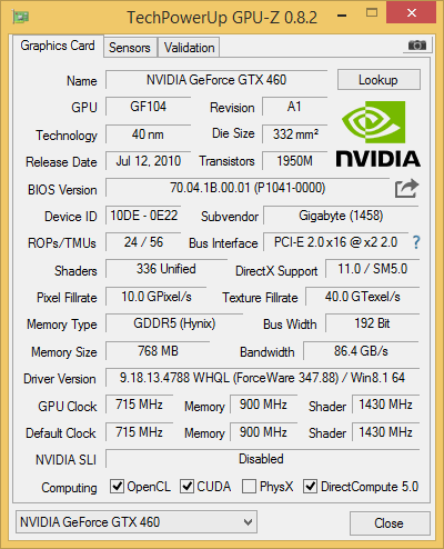
Thanks for the mods! (maybe posts 4-7 are useless and out of place?) I was thinking preserving some posts on the 1st page to include all mods there but I will create links in the first post. Corrected it on my 1st post, feel free to correct such mistakes. Now, lets get to the good staff! Till now we just speculated that x2 2.0 would work with an eGPU. How about some actual proof? I was pretty impatient if this was going to work or not and that's why I pulled together some of the stuff that I had lying around and soldered some wires from a mini pci-e to sata adapter to an x16 riser. for those of you that you are unaware, msata drives (this particular adapter is wired as of ASUS flashcon proprietary pinout) use the same pairs 23-25 and 31-33 for the SATA signal as the mini pcie pinout uses for PerT PerR signals needed for x2 mode. check below Connected all these with my old GTX460 768MB and voila... I was pretty amazed to discover that it works!!! Don't get too excited though, it seems like my solder job was poor, so although I can boot to Windows, connect an external screen on my card and capture a GPU-Z screenshot with my GTX460 @ x2 2.0, This is as far as I go. When I try to benchmark, it fails. 10-15 sec after I start the 3Dmark06 test my Nvidia Driver crashes and restarts [problem either insufficient power or most probably bad pci-e signal (maybe my poor soldering)] I am happy that it worked that way (even for a little). It seems like my quest wasn't just a ghost huntιng. This way a cheap x2 2.0 capable notebook (Sandy/Ivy/Haswell) along with a 103$ shipped PE4C v2.1 adapter and some patience could be a cheaper solution than a Macbook + 200$ thunderbolt adapter... You may noticed that my TOLUD is 2GB. I used UEFI variables to set it that low. I will describe that also.
- 807 replies
-
- 2
-
-
- dell latitude e6430
- e6430
- (and 2 more)
-
To be continued...
-
How to unlock your Flash Descriptor on a Dell Latitude E6430 (dGPU/iGPU) I carefully read post #6 by Tech Inferno Fan and Inspiron 15 schematic and realized that in order to temporarily unlock my Flash Descriptor I had to apply a High Signal (3.3V) on the SD OUT. As you can see in the schematics E6430 uses 92HD90B2X5 chip where the SD OUT pin is on pin 5. In the spoiler you can see exactly where the 92HD90B2X5 chip is located on a dGPU model. In order to reach this point you have to remove HDD (2 screws), ODD, bottom cover (3 screws), keyboard bezel, keyboard (4 screws top, 2 screws bottom), WWAN (if available 1 screw) and palm rest (2 screws top and 10 bottom). Thanks to @sskillz we know that on the iGPU model IDT chip is on the bottom side of the motherboard. Once you locate the chip the procedure is the same both on iGPU and dGPU On chip 92HD90B2X5 you can find a High Signal on pin 9 or even better the resistor that leads there (not pin 1 as on E6440). All you have to do is paperclip pin 5 and pin 9 just on boot. Then you can use fpt.exe and a FreeDos Disk to extract your original bios bin. If fpt.exe gives you error 26 then you probably didn’t succeed in applying the pinmod and you have to shutdown and try again. If you can successfully obtain your Full Bios Image you have temporarily unlocked your Flash Descriptor till you shutdown your laptop. To make the unlock permanent all you have to do mod your Flash Descriptor bios part using FITC or Flash it back and you are a free man. Now you can use FITC and set your port 1 (WWAN) to x2 2.0 mode. For x2 2.0 to work you have to use 2 mini pci-e ports: port 1 (WWAN) and port 2 (WLAN). You can use mini pci-e port 5 (under the WWAN) to connect your wifi card (tested it and working) because after turning port 1 to x2 2.0 port 2 will be disabled. I have come this far but haven’t connected a GPU @ x2 2.0 yet. Hope I have the necessary parts soon and try it. Thanks to everyone who contributed so far. Feel free to correct or contribute.
- 807 replies
-
- 3
-
-
- dell latitude e6430
- e6430
- (and 2 more)
-
The truth is that I finally found the time today to open my E6430 to unlock the Flash Descriptor. (I would dedicate a guide on how its done maybe on the 6440 thread or in a new thread) the descriptor is unlocked and port 1 runs @ x2 2.0. (port 1 WWAN & port 2 WLAN) <spoiler></spoiler> With the proper gear it will be up and running soon. I just have some hard time unlocking my ME firmware but I am probably going to ask for help from @Khenglish over at Lets enable overclocking on all 6 and 7 series laptops or it may be my 3120M (will be replace it when I have the time). I wouldn't recommend the dGPU model though. It gives me a hard time trying to connect my eGPU.
- 807 replies
-
- 2
-
-
- dell latitude e6430
- e6430
- (and 2 more)