


kondilac
-
Posts
43 -
Joined
-
Last visited
-
Days Won
1
Content Type
Profiles
Forums
Downloads
Posts posted by kondilac
-
-
8 minutes ago, timohour said:
No & no.
Only 1,2,3,4 or 5,6,7,8 (useless) for x4 and 1,2 or 3,4 or 5,6 or 7,8 for x2. You could also invert the whole array if you set x4 and use 4,3,2,1 but this is also useless unless we find a way to fully utilise port 4.
And pcie 3.0 is available on the PCH only on the newer skylake series 100.
It is also interesting that Skylake will run with DMI 3.0 and a total of 3.93GB/s compared to the 2 GB/s DMI 2.0 could do.
Thanks. What is the situation with the clock, and the two control signals when using ports as X2 or x4? Have to use them from the first port in the bundle?
-
13 minutes ago, timohour said:
I don't have the gear or the laptop to test at the moment. But i don't think this is right. If I am not mistaken the pcie lanes are connected to the PCH which according to our schematics is connected to the CPU with DMI2 x4 (data transfer rate to 2 GB/s with a ×4 link Wiki). There are also many laptops that feed their thunderbolt port from the PCH ports (AFAIK every non apple laptop do it that way). And they do true x4 (10Gbps or 16Gbps)
Yes, You are right. But an x4 PCIE connection could still seriously hog the performance of any other components connected through the MCH. Anyway, i had some free time and created the layout for the little test board checking out what's the deal with that PCIE lane @ E-Modular bay, will etch it next week, i will keep this thread posted.
Preparing for the worst case regarding PCIE4, is it possible to set PCIE 1,2,3,5 as x4? How about PCIE3 + any of 1,2,5 as x2?
-
OK so i got a big concern regarding the x4 and even the x2 eGPU thing. Since we can only access the PCIE lanes from the MCH, and that is connected to the CPU via DMI which has exactly the same transfer rate as one PCI lane (5GT/s), i guess there is no real performance benefit from aggregating more lanes from the MCH... Timohour, can you do some benchamrking x1 vs x2 to confirm this?
EDIT: I hope i was wrong, and just misinterpreted the info in Intel ARK. If the specified 5GT/s DMI is per lane, then 4xDMI2 = 20Gt/s, as Timohour stated below.
-
I modified a slim PC case, to house a HDD, VGA,and a ATX PSU. Its the same size as the e6430 with the Dell PR03X dock, which sits on the top of it. The PSU powers the lappy through the dock, besides every component inside, and is switched on/off automaticly whenthe machine is docked/undocked. Works flawless with the little script, which disconnects the GPU as a device when i undock :). It's almost ready for the paint job, just missing the cutout for the 92mm fan on the top, which is blowing the air direcly to the intake on the laptops bottom. The interior air-chambers turned out really good, also has a front USB, working power button, and audio in/out. Will post some pics when its finished
")
-
 1
1
-
-
Thanks. Since i know the dimensions and pad distance of the MPCIE i can use them to create a little PCB that i can use to experiment. This is the next thing on my todo list after finishing my docking-pod, which is near
-
12 minutes ago, timohour said:
I don't think that anybody would care. The only way is if we find this out ourselves.
I have checked through the schematics pg. 29 (a few months ago) but haven't found anything that would give an answer, so I gave up.
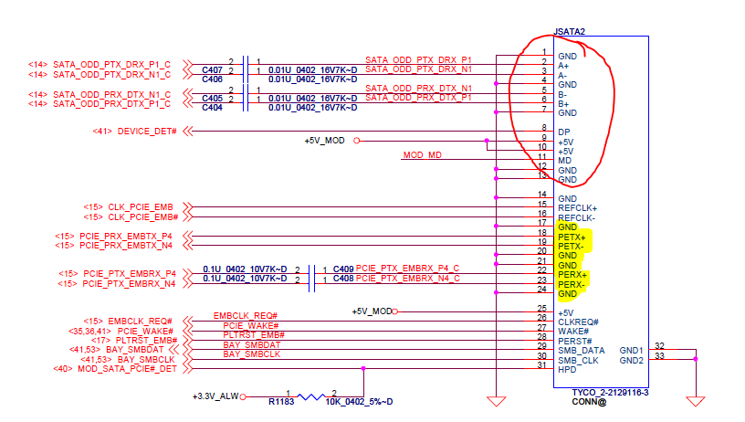
This is a ss from pg 29 where you can see the JSATA2 connector. As I have commented a while ago, this is a double sided sata odd connector. On one side is a normal sata (inside the red "circle") and the other is a unique pcie connector. The pins that I highlighted are those needed for the PCIe connection (either x2 using EC or x4 using the above mentioned). I you read the thread from the beginning there was a discussion on this matter. @sskillz also detached his JSATA 2 connector but we had no luck enabling these PCIe lanes. The answer is probably inside this P5MKF usb 3.0 bay. But I never got my hands on it. Since this was a computer I bought to use @ work I couldn't justify the extra cost on it.
I'm familiar with the experimentations describen in this thread regarding this matter, and those (including Your with the MPCIE card) only used the TX and RX signals, but not the other control signals, that's why i asked (maybe You haven't seen my edit). So i have one more question regarding this, as You noticed that a MPCIE card fits in this custom sata connector, does the pad-distance of it suit the PCIE-part of it, so i can access all the signals?
-
19 minutes ago, timohour said:
Kind of.
The changes you need to make are part of the descriptor region, not the ME. And yes you can set every combination of the following (tested myself)
port 1, 2, 3, 4 all @ x1
port 1 with 2 @ x2 port 3, 4 @ x1
port 1 with 2 @ x2 port 3 with 4 @ x2
port 1, 2, 3, 4 @ x4
Schematics show that port1 is WWAN port2 is WLAN port 3 is EC and port 4 is the modular bay.
There is no confirmation though that the modular bay is port 4 or that it can be enabled. I have been looking myself for the USB 3.0 bay to check if it is port 4 and which signal trigers its activation but I couldn't find it at a reasonable price (at least when I was searching). Also there is no hardware for the x4 connection, you need to build something yourself.
Thanks for the explanation.
Making the custom hardware is the smaller problem, port 4 is the big deal. Maybe Dell could enlighten us regarding this part...
Can You tell me what is the case with the clock, reset and wake signals in x2, and x4 setups? Can i use them from any port in the bundle?
EDIT: I dont recall this was mentioned here before, but the schematics of the e6420 also shows port4 routed to the modular bay. I'm pretty convinced now regarding if it is there or not
-
AFAIK aggregating the individual PCIE lanes to x2 or x4 must be configured in the ME FW, and not all configurations are working. Am i wrong in this?
-
Is there any progress utilizing the PCIE lane 4(E-module)? I would really like to max out my system with x4.2. Is x4 configurable using any 2 of the miniPCIE + EC + modular bay ME wise at all?
-
11 hours ago, Khenglish said:
...
I'm leaning towards incompatible vbios as the problem
...
I could sucessfully replace the IRST and LAN UEFI modules with UBU. It has options for VBIOS updating also, just in case You din't know about this tool.
-
1 hour ago, viilutaja said:
Altough I have a question about flashing modified bios back now.
Do I just use:
fpt.exe -f MODBIOS.bin
or like this in this unlocking guide... with that "-me" part also included?
fpt -me -f E6430UCME.bin
If i understand correctly you want to flash a modified ME FW, not a bios. Then you should use "fptw.exe -me -f e6430ocme.bin. The first argument is indicating that you want to flash only the ME region, and the second is that you want to Flash it.
-
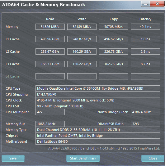
5 hours ago, timohour said:
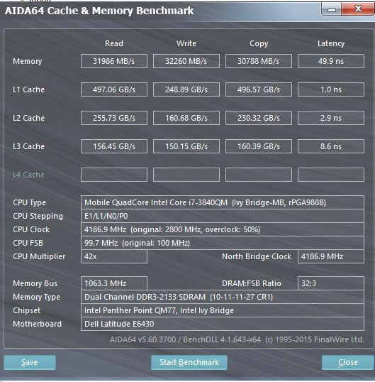
Great!!! It seems like your memory controller can perform.. Could you post some performance results when you find the sweet spot?
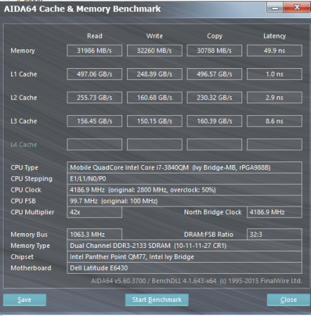
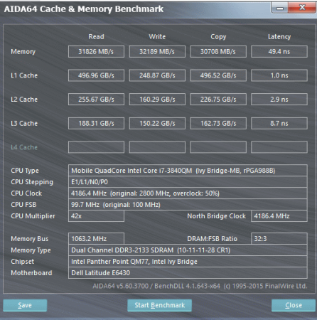
i can go down to 9-11-11-X, but it performs rorse somewhy than 10-11-11-X, the memory copy is down from 30.5k to 27k. , anything lower for tRCD and tRP than 11 doesn't boot, and , and tRAS wise i can kind of set anything (tried even 13) and it does run memtest without errors, but the setting affect the performance and latency a little bit. Latency wise 28 is the sweet spot, RW speed wise is 27. The difference is very small, but consistent across multiple benchmarks.
-
2
-
-
31 minutes ago, timohour said:
Thanks, I knew Thaiphoon, just thought that there was another one called Sharkoon. It must be an older name I was not aware of.
Try to set this to 0xFF. this worked for captnastro (just for one stick though)
Nice find! It is working indeed! I can boot at 2133 10-11-11-34, trying to tighten a bit more
-
6 minutes ago, timohour said:
Could please check the reported tRFC value with setup_var? it seems like although that's is set as an 16bit value setup_var is setting an 8bit value making it impossible to boot with tRFC = 0x16.
Try to set tRFC to 0xFF which is the maximum 8bit value. Also, where can I test the Sharkoon Burner?
Yes i have also noticed that 8bit - 16bit problem, but as i checked the default value reads out as 0x16, so i guess it is 0x116 indeed by default, there is only the problem with reading, and maybe writing it.
* Thaiphoon Burner
http://www.softnology.biz/files.html
-
19 hours ago, captnastro said:
here i still see 1T, when 0x1EE is on 0xE, even if 0x1EF is on 2T.
tried the given numbers from you. but didn't work. extracted via AIDA after CMOS reset i got other numbers:
tCL = 11 [0x1FE -> 0xB]
tRCD= 12 [0x1FF -> 0xC]
tRP = 13 [0x200 -> 0xD]
tRAS = 34 [0x201 -> 0x22]
tRC = 47 [0x209 -> 0x2F]
tRFC = 278 [0x204 ->0x116]
tRRD = 6 [0x206 ->0x6]
tWR = 16 [0x203 ->0x10]
tWTR = 8 [0x207 ->0x8]
tRTP = 8 [0x208 ->0x8]
tFAW = 27 [0x20B ->0x1B]tried those, but still, didn't work, won't boot up this way.

I checked on my system, and custom timings also doesn't work, but setting the command rate to 2T does. Do you use "thorough" boot mode? Your best chance to use custom timings for now is to write new/alter existing JEDEC profiles to the sticks, or add XMP profiles. You can do this with Thaiphoon Burner
-
1 hour ago, captnastro said:
Thanks for your answer. tried these settings, with following results:
- CMOS Reset, booting with 1 Stick @ 2133 possible. boot with 2 Sticks is not possible. Pressing PowerButton starts the System, ScreenOff, after few seconds shutdown
- setting EFI var 0x1EF to 0x2 / EFI var 0x1EE to 0x1 no boot at all, doesn't matter if 1 or 2 Sticks, ScreenOff, after few seconds shutdown
- CMOS Reset, 0x1e6 at 0x04 (1867) boot with both sticks possible. setting 0x1EE to 0x1 makes the system unbootable again. ScreenOff, after few seconds shutdown
- CMOS Reset, 0x1e6 at 0x04 (1867) boot with both sticks possible. setting 0x1EE to 0x1 and 0x1FE to 0xC makes the system unbootable again. ScreenOff, after few seconds shutdown
- CMOS Reset, 0x1EF at 0x02, 0x1EE at 0x1, 0x1E9 at 0x0, still not able to boot. ScreenOff, after few seconds shutdown
OK, one thing is sure now, if custom timings are enabled, your system wont boot. You should try CMOS reset, 1 stick only, 0x1EF to 0x2. It should boot into windows, and there you should check with CPU-Z or AIDA that the CR2 is set to 2.
After this is working properly, we should get custom timings working with 1 stick, because we know that the memory controller can run 1 stick at factory timings, first do a CMOS reset, and set the DIMM profile to custom (0x1EE to 0x1) and configure the timings to factory settings:
tCL = 11 [0x1FE -> 0xB]
tRCD= 12 [0x1FF -> 0xC]
tRP = 13 [0x200 -> 0xD]
tRAS = 35 [0x201 -> 0x23]
tRC = 48 [0x209 -> 0x30]
tRFC = 278 [0x204 ->0x116]
tRRD = 6 [0x206 ->0x6]
tWR = 17 [0x203 ->0x11]
tWTR = 9 [0x207 ->0x9]
tRTP = 9 [0x208 ->0x9]
tFAW = 27 [0x20B ->0x1B]
It should boot, but if not first double check if i done the conversion from DEC->HEX good, and the respecting EFI vars. Since these are the factory timings it should boot up fine, as if JEDEC profile.
-
16 hours ago, captnastro said:
Still not able to boot :-/ . Any advise?
UPDATE: able to boot with 1 Stick, but not with 2.
I was able to boot with my i5-3210M @2133MHZ @CR2 (setting EFI var 0x1EF to 0x2), but reboot functionality was gone as described in my old post. If i recall correctly, i had also set custom ram setting using EFI var 0x1EE to 0x1, to the command rate setting be effective.
The 3840QM had no trouble at all booting @2133 with factory timings, I guess i got a better performing one, because other users also had trouble with 2133.
First, i would make sure that the BIOS is in factory state. Removing the main battery, and then the CMOS batery for a minute will revert everything to factory settings (also the SATA mode to RAID!!!)
And then try to boot with one stick only, and then 2. Please describe the behaviour (black screen only, or you can get into BIOS, etc.) If no success, try loosening the command rate to 2.
If 2133 @CR2 does not work at all, try setting Memory Frequency, Variable: 0x1E6 to 0x4 (1867Mhz). You should be able to boot without problems, at factory timings. If this works out, and You would like to experiment, you should try setting the custom memory settings, esspecially loosening the CAS latency to 12 (I have no idea where did my post with the variables go BTW...) For this, You have to enable custom ram setting using EFI var 0x1EE to 0x1, then tCL , Variable: 0x1FE to 0xC (=12)
EDIT: Maybe try setting EFI var "DDR Selection": 0x1E9 to 0x0, to set the voltage to 1.5V instead to 1.35. Maybe the stick internally regulate the VIN to 1.35 anyway, but if not then it could help. If i will have time, i will also try this, and check if i could raise the BCLK a bit. But most likely the memory controller of the CPU is the weak part of the system, and i guess only loosening the timings will help.
-
12 minutes ago, kondilac said:
I don't like the new board

-
33 minutes ago, sefki21 said:
forgot to mention, already tried A03, same issue!
ok. i assume by again applying my modified bios dump the MW FW region will be reseted? or is there anything else to lock the ME FW region?
Yeah, works pretty well, except for that screen artifacts, i'm trying to get rid of ... got the Broadcom 4352 installed for Wifi.
This information is kind of nothing but as i recall, the HD4000 VS Hackintosh iGPU issue is caused because some memory setting of the iGPU, which can be configured using EFI vars, so if i'm correct with this then A16 could work.
I did a lot of experimenting with various bios, EC, and ME, versions (and also succesfully upgraded the intel SATA UEFI module while chasing the best performance combination) so i can provide you a dump of the BIOS only region of A07, which you can flash with intel FPTW, after disabling the bios lock by setting EFI var 0x40 to 0x0.
BUT
Without a hardware SPI programmer, if this procedure somewhy bricks your system, unbricking could be very hard, or maybe impossible without the help of Dell. Theoretically, the BIOS dump is "vanilla" factory state,so it should work but i can not guarantee it. Tell me if you want me to upload the dump.EDIT: Accordint to Timohour's post below, if this will be your last chance to get it working, first you should backup the chips raw contents with a HW programmer, and then try it maybe.
-
6 minutes ago, sefki21 said:
Hey All!
I've just upgraded from HP 2570p to the E6430 (HD+, 3840QM) and successfully OC it via PaperClip.
Now i started to experiment with Clover/OSX and almost everything works. One major problem are the screen artifacts, which are caused by my BIOS Version (read on Hackintosh-sites). Best BIOS seems to be A07. The problem is, i'm not able to downgrade anymore. Everytime i start the process it works as normal, then shutsdown and reboots normal - without installing the new BIOS (tried via Windows and via FreeDos).
Is this referred to the ME FW hack? or unlocking Flash Descriptor?
thanks in advance for your answers
")
I had the same issue, and with Timohour we narrowed down the cause for this to the ME FW "hack" kind of. But for me, downgrading to A03 worked if i recall correctly, and from there you can upgrade to A07. I would also like to experiment with OSX at some point, could You share the steps? Am i correct in the screen artifacts are caused by the memory allocation of the iGPU? Because that can be configured using EFI vars i think
-
Dewos, did you try setting the power profile to "ultra performance (max fan levels)" ? These power profiles suppiled by the Dell Feature Enhancement Pack are communicating with the embedded controller. For example, when the quiet one is enabled, my CPU also gets throttled heavily regardless the settings in TS, or the power limits set in the BIOS. I also encountered heavy throttling by using a 65W Dell adapter. Using the above mentioned ultra performance, i got no unnecessary throttling (using a 130W dell PSU ofc.)
It would be great to somehow reverse engineer what is happening under the hood between the OS and the EC when setting these profiles... I consider this bloatware (especially under w8.1, the hotkey icons are also ugly and buggy), and it would be great to have manual control over the fans, and to disable the short time power limit throttling, which is also initiated by the EC.
As i found out, the fan is capable of running even higher speed(default highest ~4000 RPM, DEEP ultraprofile highest ~4500RPM), using SpeedFan, setting the fan to 100% results in ~4800RPM if i remember correctly, but after a split second the EC resets the speed to its own setting. While investigating the possibilities to gain full control over the fan i got an interesting finding, on some dell machines there is a hidden engineering menu accessable by a keyboard sequence (Hold FN + Shift, press 1, 5, 3, 2, 4 Release FN+ Shift, Press FN + R) which does not work on the e6430 for me, but the first part of the sequence has some effect, because the caps lock lights up for a seecond... The EC Fan control can be disabled in this engineering menu on other machines, to gain full control with Speedfan
-
1 hour ago, viilutaja said:
I read this thread from the beginning many times before, thats why I decided to purchase this laptop at first place. I did not make a post about my problem without reading through the thread. There was no hint in first post to enabling Optimus through EFI shell hack... or did i miss that somehow :/ ?
In my case, the necessary settings in the BIOS was only the ones regarding the iGPU state (the two variables i mentioned before), i did not touch the Optimus settings. I assumed that you did not read the first post, because you were looking for non existing options in the bios, which can be only set through EFI vars, and it is well documented in this thread, and you seem like you have never encountered with the whole thing before (requesting link, and instructions)
-
How to make a permanent boot option to EFI Shell
This guide is for advanced users only, i take no responsibility for any damage caused by doing this
First determine the disk, and partition number of the EFI system partition. This can be checked using disk management in windows computer management
- Press Windows + r
- run compmgmt.msc
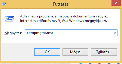
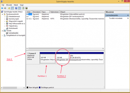
Then run "DISKPART" through an elevated command prompt, and assign a drive letter for the EFI partition with the following commands:
select disk X
select partition Y
assign
Where:
- X is the number of the disk which has the EFI system partition
- Y is the number of the EFI system partition on the disk
(In my example, X = 0, Y = 2)
The EFI partition will be now accessible using your favourite file manager if it has administrator privileges.
Obtain a copy of the EFI shell from here and unpack the contents of the archive to the EFI partition in the following folder: /EFI/BootNow reboot the machine and get into the BIOS, and add a new boot entry. You name it as you want, and select the "bootx64.efi" file from the location you previously copied it.
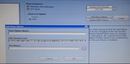
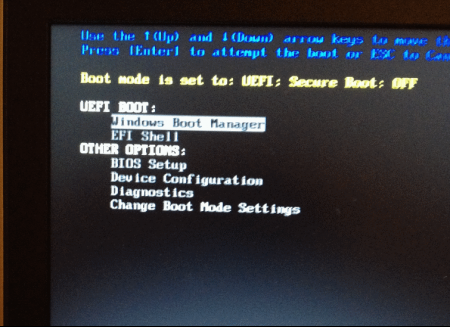
From now on, you can boot into the EFI shell anytime you want, after selecting it from the boot menu (press F12 at boot)
Pro tip for lazy users like me:
The normal bios options can be changed using the Dell Command | Configure tool from the OS. Reboot required, mangling with the laggy bios interface isn't
-
1
-
3 hours ago, timohour said:
while in your E6430 score there is no secondary GPU as noticed by @Tech Inferno Fan above.
Check the two secondary GPU dropdown menus http://www.3dmark.com/fs/7139888
Since you have already disabled the dGPU-s root port,in order to get optimus working, iGPU must be set to always on, and set to primary.
These settings like most of the advanced ones are not available from the BIOS, and can only be modified through EFI variables, which are accessable through an EFI shell.
You can make a bootable thumbdrive with it, or follow the steps in my next post.
You should set EFI var 0x1d4 to 0x0, and 0x1d8 to 0x1.No offense, but I highly recommend for you to read this whole thread because the advanced user base of this machine provided a great deal of useful information (everything about the accessibility of the advanced BIOS options through EFI shell also), but at least you should read the first post before asking questions which were answered many times before.
In my next post i will describe how to make a permanent boot option to get into EFI shell, but it will involve messing with the EFI system partition with wich one can easily brick his current OS boot so it is only for advanced users who know what are they doing, and i take no responsibility for anything.-
1
-


14" Dell Latitude E6430 - Performance Upgrades and System Mods
in Dell Latitude, Vostro, and Precision
Posted
With an unlocked FD, and disabled bios lock (0x40->0x0) I had no problems flashing the BIOS region with FPT