kondilac
-
Posts
43 -
Joined
-
Last visited
-
Days Won
1
kondilac's Achievements
T|I Semi Advanced (3/7)
24
Reputation
-
With an unlocked FD, and disabled bios lock (0x40->0x0) I had no problems flashing the BIOS region with FPT
- 807 replies
-
- 1
-

-
- dell latitude e6430
- e6430
- (and 2 more)
-
Thanks. What is the situation with the clock, and the two control signals when using ports as X2 or x4? Have to use them from the first port in the bundle?
-
Yes, You are right. But an x4 PCIE connection could still seriously hog the performance of any other components connected through the MCH. Anyway, i had some free time and created the layout for the little test board checking out what's the deal with that PCIE lane @ E-Modular bay, will etch it next week, i will keep this thread posted. Preparing for the worst case regarding PCIE4, is it possible to set PCIE 1,2,3,5 as x4? How about PCIE3 + any of 1,2,5 as x2?
-
OK so i got a big concern regarding the x4 and even the x2 eGPU thing. Since we can only access the PCIE lanes from the MCH, and that is connected to the CPU via DMI which has exactly the same transfer rate as one PCI lane (5GT/s), i guess there is no real performance benefit from aggregating more lanes from the MCH... Timohour, can you do some benchamrking x1 vs x2 to confirm this? EDIT: I hope i was wrong, and just misinterpreted the info in Intel ARK. If the specified 5GT/s DMI is per lane, then 4xDMI2 = 20Gt/s, as Timohour stated below.
-
I modified a slim PC case, to house a HDD, VGA,and a ATX PSU. Its the same size as the e6430 with the Dell PR03X dock, which sits on the top of it. The PSU powers the lappy through the dock, besides every component inside, and is switched on/off automaticly whenthe machine is docked/undocked. Works flawless with the little script, which disconnects the GPU as a device when i undock :). It's almost ready for the paint job, just missing the cutout for the 92mm fan on the top, which is blowing the air direcly to the intake on the laptops bottom. The interior air-chambers turned out really good, also has a front USB, working power button, and audio in/out. Will post some pics when its finished
- 807 replies
-
- 1
-
-
- dell latitude e6430
- e6430
- (and 2 more)
-
Thanks. Since i know the dimensions and pad distance of the MPCIE i can use them to create a little PCB that i can use to experiment. This is the next thing on my todo list after finishing my docking-pod, which is near
-
I'm familiar with the experimentations describen in this thread regarding this matter, and those (including Your with the MPCIE card) only used the TX and RX signals, but not the other control signals, that's why i asked (maybe You haven't seen my edit). So i have one more question regarding this, as You noticed that a MPCIE card fits in this custom sata connector, does the pad-distance of it suit the PCIE-part of it, so i can access all the signals?
-
Thanks for the explanation. Making the custom hardware is the smaller problem, port 4 is the big deal. Maybe Dell could enlighten us regarding this part... Can You tell me what is the case with the clock, reset and wake signals in x2, and x4 setups? Can i use them from any port in the bundle? EDIT: I dont recall this was mentioned here before, but the schematics of the e6420 also shows port4 routed to the modular bay. I'm pretty convinced now regarding if it is there or not
-
AFAIK aggregating the individual PCIE lanes to x2 or x4 must be configured in the ME FW, and not all configurations are working. Am i wrong in this?
-
Is there any progress utilizing the PCIE lane 4(E-module)? I would really like to max out my system with x4.2. Is x4 configurable using any 2 of the miniPCIE + EC + modular bay ME wise at all?
-
I could sucessfully replace the IRST and LAN UEFI modules with UBU. It has options for VBIOS updating also, just in case You din't know about this tool.
-
If i understand correctly you want to flash a modified ME FW, not a bios. Then you should use "fptw.exe -me -f e6430ocme.bin. The first argument is indicating that you want to flash only the ME region, and the second is that you want to Flash it.
-
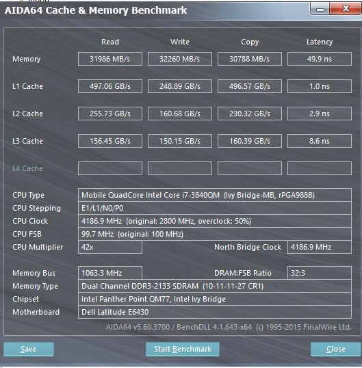
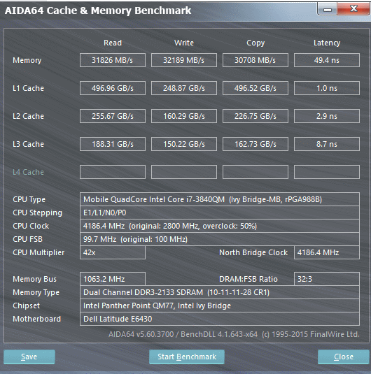
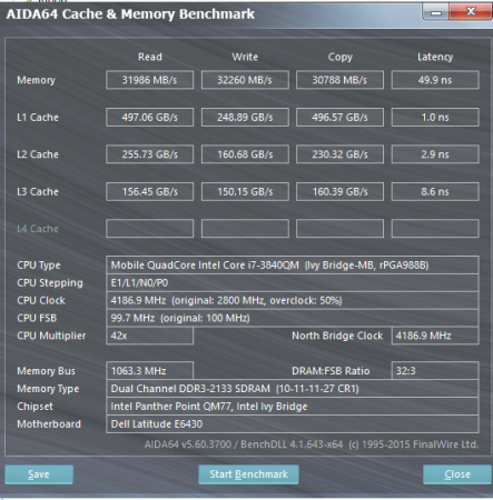
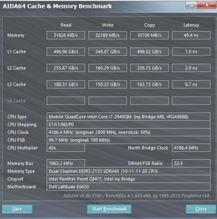
i can go down to 9-11-11-X, but it performs rorse somewhy than 10-11-11-X, the memory copy is down from 30.5k to 27k. , anything lower for tRCD and tRP than 11 doesn't boot, and , and tRAS wise i can kind of set anything (tried even 13) and it does run memtest without errors, but the setting affect the performance and latency a little bit. Latency wise 28 is the sweet spot, RW speed wise is 27. The difference is very small, but consistent across multiple benchmarks.
- 807 replies
-
- 2
-
-
- dell latitude e6430
- e6430
- (and 2 more)
-
Nice find! It is working indeed! I can boot at 2133 10-11-11-34, trying to tighten a bit more
-
Yes i have also noticed that 8bit - 16bit problem, but as i checked the default value reads out as 0x16, so i guess it is 0x116 indeed by default, there is only the problem with reading, and maybe writing it. * Thaiphoon Burner http://www.softnology.biz/files.html