


euqlaog
-
Posts
0 -
Joined
-
Last visited
-
Days Won
27
Content Type
Profiles
Forums
Downloads
Posts posted by euqlaog
-
-
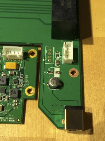
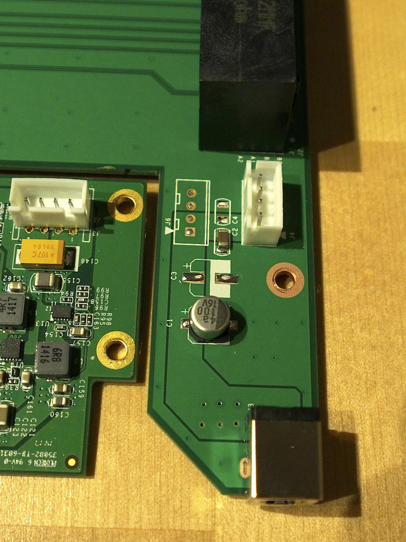
Easiest is to put the multimeter probe in the PCIe slot pin2. That is 12V on either side of the slot as shown at :: ST-Service ( . Then probe on the circuit to see where that 12V point starts. If it starts on the upper side of the C2 component, then the 12V is straight through from the DC jack. If it's from the bottom side of C2 then C2 is a fuse which detects power draw and shuts down if it exceeds the fuse rating, presumably 25W.
Another basic test, if the bottom side of C2 is GND then it's not a fuse but rather something else.
What is "upper" and "bottom" side of the C2? I was only able to make beep sound by touching the PCIe riser 2nd gold finger, and randomly. Changing the direction (black/red probe) or restarting the multimeter may help to make sound again. Touching also C3 or the base of DC jack gave a beep sound occasionally when the other probe was touching PCIe 2nd gold finger, does it proof something?
EDIT: I was also able to make a short beep sound by touching 2nd PCIe solder point on the rear side without using PCIe riser, but easier to test when both continuity test points are on the same side.
-
How is your experience of a 15" i5 or i7 MBPr during gaming load in Windows? I would guess it get's pretty noisy. Are you running that MacBook on a "stand" for fresh air underneath it or maybe sth like a notebook cooler with a fan underneath the MBP?
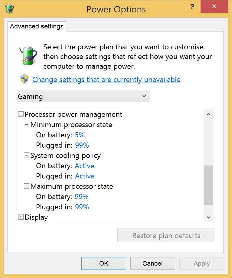
The mid 2014 MacBook Pro 15" Iris only is completely silent during gaming when using power options settings as shown below (disables the Turbo Boost up to 3.4Ghz that causes fan noise on CPU intensive games).

Silverstone 450W SFX PSU is a bit noisy. If you use Corsair RM550 (fan don't spin at all), GPU fans are the only part that makes some noise.
-
Your test confirms that the DC jack supplies direct power into the PCIe slot, which is the simplest and most appropriate routing for where a large portion of power goes.
I too don't see any tracks leading to the 12V pci-e slot pins. More likely then is they are using a hidden 12V plane on the multilayer board. 12V coming in via the DC jack, then applying the C2 fuse to route it the hidden layer.
Please do a continuity test to the 12V pcie port pin2 (either side) to what looks like a fuse point (C2) bottom edge to confirm. Ref PCI Express - Wikipedia, the free encyclopedia. Also do a continuity test from the 12V 4-pin input jack (J4). They might be routing down via those pins as well.
If C2 is a fuse then it would be a problem The fuse would stop power once it gets over 25W, requiring a solder bridge across it, or the C4 that looks to mirror it, as a workaround. That may explain why GTX750 cards without pci-e slot power don't work and we've had some limited success with other cards. 25W would give hit-and-miss results. We need to be able to supply up to 75W to the pcie slot per PCI SIG spec.
As mentioned, the yellow/black cable runs 12V to TB board. It supplies power for the TB circuitry. There it would be stepped down to 3.3V for components, and 18V/10W per TB port as bus power. Thunderbolt (interface) - Wikipedia, the free encyclopedia
So given the 60W AC adapter, 25W is specced for the pcie slot. Sounds about right. 10W + 10W for the Thunderbolt ports, 10W for the TB circuit components, 5W for losses due to conversion adds to 35W, leaving 25W for the slot.
Thank you very much for your analysis!!
 I did those continuity tests with a multimeter. Wasn't sure what is the PCIe port pin2 on the board solder points, so I plugged in PCIe riser half way to be able to touch the correct golden finger. And of course all the power off, when doing continuity test. The result was a very short beep sound, so there is continuity from both C2 (upper & lower pad) and J4 (both 12V pins) to the PCIe port pin2. How can we be sure whether the C2 is power limiting fuse? I try to be very careful when doing these tests so that I won't break anything... It would be great to bypass that likely 25W limit.
EDIT: clarified with bolded text
-
Can you take a photo of the reverse side of this board? I'm specifically looking to see if there are tracks leading from the DC jack to the PCIe slot.
From the picture you have above, there are no power tracks leading to the PCIe slot from the DC jack. Instead, 12V power is routed via the TB board and what looks to be back out via the small edge connector to the PCIe board. A picture of the reverse side of DC jack/PCIe slot board would confirm that.
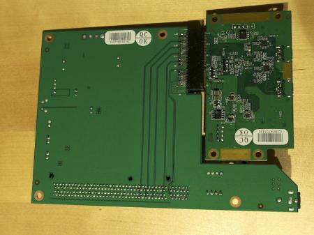
I cannot see any power tracks leading to the PCIe slot, but according to my tests there has to be a connection that is not clearly visible (on the edges or inside the board). When I remove the DC barrel plug in the case where power comes also from self made 4-pin cable to the TB card, Windows crashes. A barrel plug is compulsory in order to detect GPU when not using a powered PCIe riser. It may be possible to solder 12V power points beginning from DC jack, but I don't recommend it. More practical and safe is to use an adapter to barrel plug with correct polarity and voltage.
-
 1
1
-
-
At least this cable can be used to experiment, to cut the wires and connect them to the molex black an yellow pins.
Goalque, can you test this setup?
I quickly made a test cable (+12V, +12V, ground, ground) using a C-LINK cable from my modular Corsair ATX PSU, which has identical pins but the connector is different (I was able to fit it just enough to feed power). Other end connected to the 12V Molex. These are the results:
- power from self made 4-pin cable to the TB card -> GPU NOT detected in device manager (lights turn on, blue thunderbolt light too)
- power from self made 4-pin cable to the TB card + powered PCIe by 12V molex riser -> the same as above
- power from self made 4-pin cable to the TB card + self made barrel plug attached -> GPU detected, external screen works, but no Optimus
- power from barrel plug + 4-pin original cable attached at both ends as it should be -> GPU detected, Optimus detected
All of these tests done by using a x16 PCIe riser (molex plugged/unplugged) + Gigabyte 750Ti + its 6-pin power.
-
3
-
-
So, is there this 3rd option?
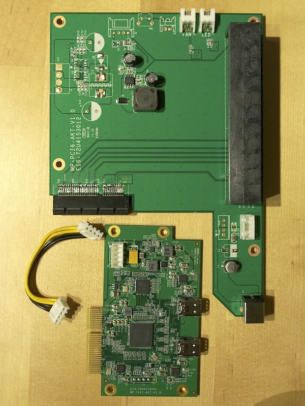
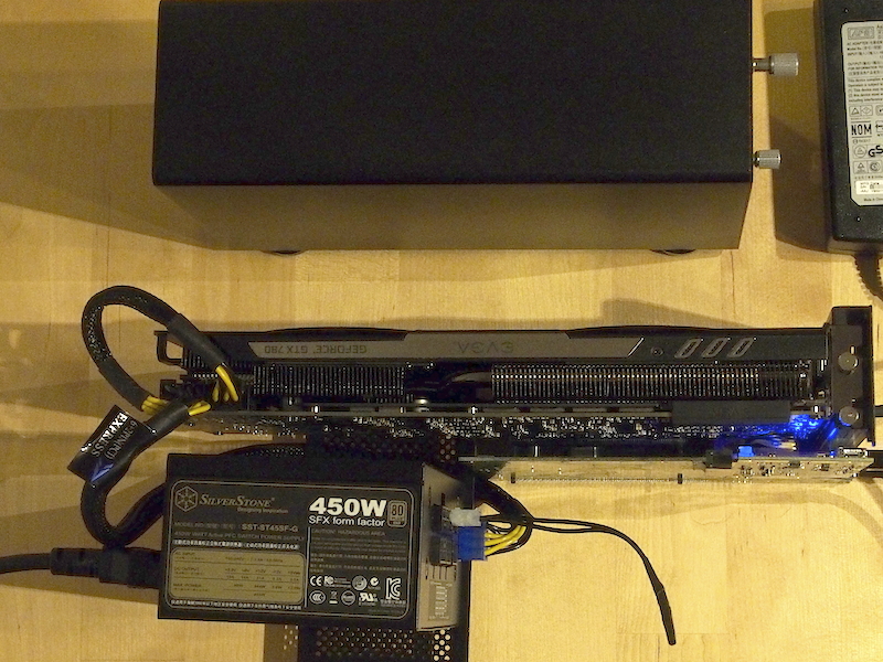
3. Do not use a x16 pcie powered riser, connect only the 6-pin or 8-pin pcie power cable to the GPU and create some kind of connector for the daughter board. As it is seen from the picture below the daughter board connector has 2 yellow and 2 black cables, similar to the 4-pin ATX CPU connector. Can the daughter board be powered by a 4-pin ATX CPU connector if the necessary cable soldering/connections are done? I mean cutting the end of an ATX CPU cable, cutting one end of the existing daughter board cable and connecting the loose cables respecting the color of the cables. Will it work?
I have actually examined the 3rd option, referring to my earlier question: "Does anyone know why the 4-pin power cable to the thunderbolt card has to be connected when using a powered riser? Lights turn on, but GPU is not detected."
So far, I have no answer. Without this little cable, device manager doesn't see my external GPU when I have powered it with a 12V x16 PCIe raiser. I have measured with a multimeter if there is power coming out from the 4-pin connector on the PCIe board. When power is on through 12V riser (DC barrel plug unattached), both the yellow cable pins are approximately +2V, and blacks seems being ground (0V). But there remains some 0.5-1V voltage even though the whole system is shut down. Therefore, it is possible that this cable has some other meaning as well than just feed power. I am not not an electrical engineer, and I am not going to cut those wires
 So here are more detailed photos for those who are interested
-
4
-
-
I tried reinstalling the Nvidia drivers but still the 750 Ti doesn't work. You are right about, it is the EVGA 750 Ti SC without the 6 pin connector.
My Gigabyte 750Ti works with a MacBook Pro Iris on Win8.1 with 6-pin power cable plugged (but doesn't fit inside the enclosure). 750Ti fans spin at full speed before starting the computer, which is quite annoying. The differences are that you use a NUC and your GPU is only PCIe powered.
-
1
-
-
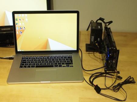
@goalque, you're the first to do a 15" Macbook Pro + GTX780@16Gbs-TB2 eGPU implementation using a AKiTiO Thunder2 PCIe Box + ATX PSU + molex-to-barrel adapter. You also didn't use a PCIe riser, but instead plugged straight into the AKiTiO box. This being a significant development over the Sonnet enclosures that did need a PCIe riser due to slot/chassis constraints.
Would you like to do a full implementation report of how you did it, along with benchmark results? This is a first and would be very helpful to others wanting to do the same as have all user submitted implementation reports. I'm happy to help you with the formatting of it if you like. Thanks.
I have been searching the most inexpensive TB2 eGPU setup for my new 15” MacBook Pro and this beats indeed other Thunderbolt 2 enclosures for external GPU purposes at the moment. I have gathered all the knowledge from this and other web sites, especially from here http://forum.techinferno.com/diy-e-gpu-projects/6918-updated-2013-13-15-macbook-pro-thunderbolt-2-egpu-plug-play-optimus.html#post94929
Do you mean that it’s better to create a new thread of this implementation or just edit my pictured post to be more detailed? Can you list what benchmark testing? Is there a template or an example how to make a full report? I can take that task when I have some free time. There is not much to say, because it’s a standard Boot Camp Windows 8.1 installation and all you need is those components. Almost plug and play. English is not my native language, so before I post it, you could proofread and make some formatting.
This is my side project, but my plans have not yet stopped here. I will continue with the enclosure design and have contacted some manufacturers, but unfortunately most of them don’t sell single units, and if do, they are not located in Europe. I don’t want to pay the extra VAT. But I found one - they have metal and plastic cutting service with laser, and no minimum order limit. If you draw dashed cutting lines, those parts can be easily bent by hand if the thickness is under 2mm. And aluminium is more easier to bend than steel. It might be possible to replace both the inner chassis and outer shell to support full length graphics cards. My final setup most likely will be a tower model and SFX PSU fitted inside. I will examine it more later on. One very worthy post from ithildin:
However, it seems to be a standard extruded aluminium project box painted black (plus a set of feet) so I should be able to replace it with a common project case with similar dimensions.This gives us the option to replace the outer shell with a wider case so long as new front+back plates are designed with matching cutouts for Thunderbolt ports/vent,etc. -
You're welcome Sachin10. I gave some instructions in my first post of this thread to enable Optimus, but it depends on the chosen graphics card. Once got it working, it should be like plug and play. 3DMark11 score with internal display was a bit lower than external, but still very efficient to play GPU and CPU intensive games with retina display only.
-
Yes, I own a Thunder2 PCIe Box. Still can't get it to work with my 750 Ti even with a 16x PCIe riser extender with molex plug.
But I managed to get it to work with a HD 7870 connected to an Intel Thunderbolt NUC running on Win8.1/EFI.
Take a look at this thread. Try also reinstalling Nvidia drivers. I guess your 750 Ti doesn't have 6pin or 8pin connectors on the side?
-
I have ordered all my parts, as well as a Galaxy 770. What is the OSX workaround for this setup? Goalque that setup looks stellar! I'm going to be tossing mine into a CM 120 Advanced Mini Itx Case. Can you tell me how you took out the AKITIO board of the enclosure??
Thanks! The workaround is described here:
I just used a screwdriver, no other tools required to take out the board and back panel. Good luck with your Galaxy 770!
-
CONFIGURATION
- Apple MacBook Pro 15" Retina / 256GB / 16GB (Mid 2014), with Iris Pro graphics only
- AKiTiO Thunder2 PCIe Box
- Silverstone Strider ST45SF-G 450W 80+ Gold Modular Power Supply (v. 2.0)
- Self made connector to power up PSU ("paperclip trick")
- EVGA GeForce GTX 780 6GB SC w/ EVGA ACX Cooler
- Apple 2m Thunderbolt Cable
SOFTWARE INSTALLING
- Install Windows 8.1 64 bit from a USB stick by using ISO file. This is a standard Boot Camp installation.
- After installing Windows, download and install all Windows updates.
- Update Boot Camp drivers (Boot Camp Support Software 5.1.5640) and shut down
- Do the hardware preparing part 1-8
- Install Nvidia driver 340.52 (Drivers | GeForce)
- Shut down MacBook Pro and continue from the hardware preparing step 8
HARDWARE PREPARING
- Open AKiTiO's box by a normal screwdriver, take out the PCIe board and attach the GPU to its x16 slot
- Attach PSU's power cable (blue) to the GPU and do the "paperclip trick" as shown in picture 1.
- Attach DVI/HDMI cable to the GPU (if using a back bracket, I wasn't able to fit DVI-cable because the plastic part was too wide) and use any external monitor you like
- Place something under the GPU so that it will be steady (a removed front panel is perfect for this)
- Attach AKiTiO's 60W power plug to the DC jack of the PCIe board
- Connect TB cable
- Power up AKiTiO's box (green light should appear) and the PSU at the same time (I use a power strip with a switch on the floor)
- Turn on MacBook Pro (blue light should appear). If it is booting to OSX partition, change startup disk to Boot Camp partition from the OSX preferences.
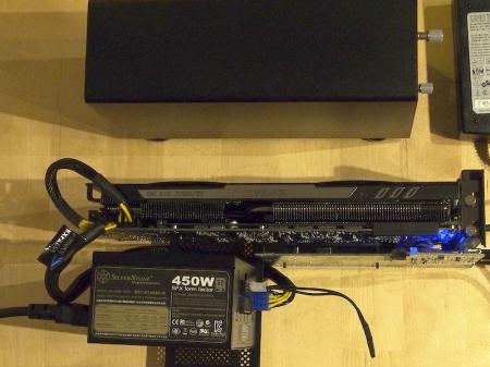
Picture 1.
After a few seconds Windows login screen should appear. If it shows up in the internal (retina) screen and a waiting circle seems to be a little slow, as well keyboard inputs to the username/password fields, this is good news. You have optimus enabled and both screens will work smoothly after logged in.
What if the exernal screen is working only and internal is black? This is nothing to be worried about. The GPU will work at full performance, but if you like to try enabling internal screen and do some 3K gaming, do the following:
- Go to the screen resolution settings (Control panel > Appearance and Personalisation > Display > Screen resolution), and select "extend these displays", drag your internal screen to the left side if it is not there yet and check "make this my main display".
- Shut down your MacBook Pro
- Wait about 10 seconds
- Turn on your MacBook Pro (by keeping alt/option key pressed down, and quickly select the Windows partition)
- If the internal screen stays black, try again from step 1
When you have enabled Optimus, do not select "restart", instead always select "shut down", because restarting might disable the Optimus.
There are three power solutions at the moment, choose only one of them
1) By using self made Molex to barrel (2.5mm/5.5mm) plug adapter. The GPU is attached directly into x16 slot. No need for AKiTiO's 60W power adapter. Take into account that power goes through the TB card and x4 slot, which is specified to carry only 25W, but according to my power consumption tests it is able to eat much more. This does work for most of the GPUs as they don't seem to use that 75W. A powered riser is preferred, because we don't know how safe this is with more power consuming GPUs from x16 slot. However, if you choose this method, please protect the 4-pin cable connecting the TB card and PCIe board.
Picture 2.
2) A non-back-powered riser + molex-to-barrel adapter.
3) A back-powered riser. If you choose this, nothing shouldn't be attached to DC jack of PCIe board.
PERFORMANCE
Note: The new Intel Core i7-4770HQ 2200Mhz CPU is not recognized correctly
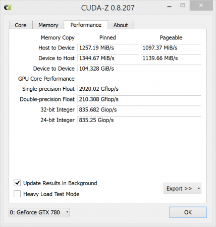
3DMark06: 25688
3DMark Vantage (graphics): 37776
3DMark11 (graphics): 11832
3DMark Fire Strike (graphics): 9431
Unigine Heaven Benchmark 4.0: Direct3D9/1280x720 2xAA windowed/Basic: 2580 (FPS 102.4)
Unigine Heaven Benchmark 4.0: Direct3D11/1600x900 8XAA windowed/Extreme: 1488 (FPS 59.1)
CUDA-Z
GAMING (FPS)
GAMING (FPS)
Tomb Raider (performance test, default high/ultra/ultimate settings)Retina 1920 x 1080 External 1920 x 1080 high 129,7 high 161,2 ultra 92,2 ultra 111,2 ultimate 63,2 ultimate 72,5 Retina 2880 x 1800 4K monitor (3840 x 2160) high 62,3 high 54,4 ** ultra 50 ultra 37,2 ** ultimate 35,3 * ultimate 27,1 **
Battle Field 4 (test range)
Retina 1920 x 1080 External 1920 x 1080 medium 98 medium 167 high 61 high 84 ultra 54 ultra 70 Retina 2880 x 1800 4K monitor (3840 x 2160) medium 61 medium 61 ** high 31 high 18 ** ultra 26 ultra 16 ** *) maximum power consumption ~ 185W PSU (measured) + 60W AKiTiO's power adapter (not measured) ~ 245W
**) Samsung UHD 28" Monitor, powered riser (method 3), and Nvidia driver 344.65
I really like this setup, you have the portability of a laptop combined to higher end graphics at home. There might be a workaround for OSX as well that I will test some day.
-
11
-
So if using a GTX 760 (max power 170W) one wouldn't need the powered riser? It uses two 6-pin plugs so that's 75W + 75W + 25W (from PCIe) = 175W. Is that cutting it too close?
If GTX 760 doesn't draw more than 175W, I think that you don't need a powered riser, given that 25W is enough from the PCIe such as it is for GTX 780. ATX/SFX PSU is needed in this situation. With a normal computer motherboard, x16 PCIe 2.0 slot outputs up to 75W, but I couldn't find any information if some graphics cards require that max 75W.
By the way, I am still not sure about 25W limit, because 750Ti model I am using, requires that 6-pin plug according to this:
Gigabyte GTX 750 Ti OC review | Graphics cards Reviews | TechRadar, but there exist cards that don't have this connector (EVGA - Products - EVGA GeForce GTX 750 Ti - 02G-P4-3751-KR).
I am planning to make a custom box without powered riser, because the double width back panel is removable and therefore making a longer enclosure much easier (but have to make holes to attach AKiTiO's card combination to the side). Not yet sure, if I will use a SFX or ATX size PSU inside. Because the GPU and thunderbolt controller are very close together, some fan in front of the box is needed to avoid heat problems.
-
I can confirm that Optimus works at least with EVGA GeForce GTX 780 and Gigabyte's 750Ti on Windows 8.1. I have the MacBook Pro with an Iris Pro only. After a straight reboot internal display remains black with GTX 780 (external display is recognised always), but works again after a few tries as I go to display settings and check "make this my main display", shut down, restart with alt/option key down and then select a Windows partition quickly. Anyway, after the first successful retina display detection, shutting down, waiting for a few seconds, and then restarting seems to be the most preferred way with GTX 780.
Powered riser is not required, but if you use it, AKiTiO's power supply is not necessary. You can take out the backplane + thunderbolt card from the box and put full length, more powerful GPU directly connected to the x16 slot and use AKiTiO's power supply as it is or 12V Molex to 5.5/2.5mm barrel plug adapter cable from ATX PSU. Unfortunately it seems that there is that 25W limit, so that 750Ti cannot work without connecting 6pin power plug. I tried with my own 12V barrel plug which should feed enough power (if making this kind of cable, make sure that you are using correct polarity and test it with multimeter). Anyway, great news is that GTX 780 works with 8pin + 6pin plugs connected (150W + 75W) and the rest 25W from the PCIe slot, maximum total power is 250W which is just enough for GTX 780.
Does anyone know why the 4-pin power cable to the thunderbolt card has to be connected when using a powered riser? Lights turn on, but GPU is not detected.
-
5
-


US$189 AKiTiO Thunder2 PCIe Box (16Gbps-TB2)
in Enclosures and Adapters
Posted
Red arrows on the picture represent multimeter's red probes and black arrows are black probes. Red ellipses are +12V and blacks are ground except the C2 where multimeter shows -12V. Yellow rectangle is the 2nd golden finger of PCIe x16 riser. Any thoughts about this? Thanks!