


euqlaog
-
Posts
0 -
Joined
-
Last visited
-
Days Won
27
Content Type
Profiles
Forums
Downloads
Everything posted by euqlaog
-
US$189 AKiTiO Thunder2 PCIe Box (16Gbps-TB2)
euqlaog replied to Tech Inferno Fan's topic in Enclosures and Adapters
My Gigabyte 750Ti (PCIe + 6pin powered) and EVGA GTX 780 are both stable, but only the latter is now fully tested (you can see the performance numbers from my updated post, retina screen playing is very smooth and no stability problems at all). There are so many variables. I guess too, that it is vendor specific. Firstly, you have to choose the right vendor, and secondly the card must have at least one 6pin power connector. By solving the 25W limit of the PCIe slot, we very likely extend the collection of supported GPUs. -
I just updated my earlier post: http://forum.techinferno.com/diy-e-gpu-projects/7453-akitio-thunder2-pcie-box-fully-support-macbook-pro-15-iris-model-3.html#post103029
-
US$189 AKiTiO Thunder2 PCIe Box (16Gbps-TB2)
euqlaog replied to Tech Inferno Fan's topic in Enclosures and Adapters
Yes, my implementation requires Windows 8.1 Boot Camp installation. Not sure about Windows 7, because I haven't tested it. May be possible that it doesn't work. -
US$189 AKiTiO Thunder2 PCIe Box (16Gbps-TB2)
euqlaog replied to Tech Inferno Fan's topic in Enclosures and Adapters
Very stable. I have done performance tests that I will post here soon, and some occasional gaming. Some games running on 2880 x 1800 native resolution. -
US$189 AKiTiO Thunder2 PCIe Box (16Gbps-TB2)
euqlaog replied to Tech Inferno Fan's topic in Enclosures and Adapters
EVGA - Products - EVGA GeForce GTX 780 6GB SC w/ EVGA ACX Cooler - 06G-P4-3787-KR -
US$189 AKiTiO Thunder2 PCIe Box (16Gbps-TB2)
euqlaog replied to Tech Inferno Fan's topic in Enclosures and Adapters
Your earlier post gave a bit hope that you managed to get R9 290 working? </quote=dernils;103273><quote=dernils;103273>- Can you say what 550W power supply did you use? - Did you use a "paperclip" method to power up PSU and what kind of x16 to x16 powered riser? There exist risers that don't have black ground wires. I used one with two yellow + two black wires + capacitor. - Windows 8.1 Boot Camp installation? I bought mine also from MacWay in France. </quote=dernils;103273> -
US$189 AKiTiO Thunder2 PCIe Box (16Gbps-TB2)
euqlaog replied to Tech Inferno Fan's topic in Enclosures and Adapters
Yes, I was just very lucky with my selected GTX 780 as it doesn't need more than 25W from the x16 slot. Works for me at the moment and I will update my test results and put more detailed instructions in near future. I was very curious to know if there are other solutions to provide that 75W, so that people here may have more luck with other GPUs too If there is a workable and safe solution without much soldering, I may try it one day. The 4-pin yellow/black cable is still compulsory in this test too, and you cannot use the powered riser and power from DC jack (also by using AKiTiO's power adapter) at the same time because in that case, when starting 3DMark11 test, your system will shut down. -
US$189 AKiTiO Thunder2 PCIe Box (16Gbps-TB2)
euqlaog replied to Tech Inferno Fan's topic in Enclosures and Adapters
I double checked the x4 slot and was so sure that made a real test by a x4-male to x16-female molex-powered raiser, x16 end directly attached to the TB card, and x4 to the PCIe board. It worked perfectly with my GTX 780 and passed 3DMark11 test with similar results as earlier. One important note: the GPU has to be powered via the raiser only. I do not recommend this as a solution, because it may be unsafe. As far as I know, x4 slot is specified to feed max 25W (http://en.wikipedia.org/wiki/PCI_Express). Even though PSU 12V rail is able to give more, it could be unsafe. I don't want melted wires. We need 6-pin power plug to feed 75W to the x16 via the PCIe board rails somehow, am I right Tech Inferno Fan? One way is two 4-pin molex plugs to one 6-pin plug adapter as well, and I think I have one. But the question is, how can we provide 75W to the PCIe slot safely? I am a bit worried also about those little holes beside the x4 slot, how much power they can eat safely. Thanks for all here who have helped me to this point, and hopefully my tests give some great ideas for your future implementations. I myself stay with the solution I have at the moment; no powered risers, no soldering and no AKiTiO's power adapter. -
US$189 AKiTiO Thunder2 PCIe Box (16Gbps-TB2)
euqlaog replied to Tech Inferno Fan's topic in Enclosures and Adapters
Yes, TB technology looks similar. That card works as a host device, but AKiTiO's one is working in target mode. What would be our next step? -
US$189 AKiTiO Thunder2 PCIe Box (16Gbps-TB2)
euqlaog replied to Tech Inferno Fan's topic in Enclosures and Adapters
Ok, thanks! I was actually referring what ithildin said: "I would be really great if we could replace the PCIe adapter board entirely, both for warranty concerns and also for powering hungrier GPUs without issues." -
US$189 AKiTiO Thunder2 PCIe Box (16Gbps-TB2)
euqlaog replied to Tech Inferno Fan's topic in Enclosures and Adapters
I already have a self made molex to 4-pin yellow/black cable to the TB card, and I have tested it. Look at here. A standard 4-pin floppy molex plug was a little too big (but the holes seemed to have correct positions with the TB card's 4 pins). Those test results make me think that we need some kind of "loop" connection via the 4-pin yellow/black cable to the x16 PCIe slot. I still don't know what is the meaning of a very short beep sound when I did that continuity test from near DC jack points to the x16 PCIe 2nd pin. So before bypassing the PCIe board entirely, feeding 75W from the x4 connector to the x16 slot may be more workable solution. EDIT: For those who are interested about female-to-female-board/riser-solution, I found these: http://www.boston.co.uk/products/components/c.$1655$7120/default.aspx PCIe x8 1.0 Expansion Backplane (184) | MaxExpansion.com RSC-R2UT-2E8R looks quite interesting. I asked from them, and it has a 6-pin power connector (75W). This is just an idea... but would they help in theory? If not, maybe they can be used for SLI mode or for fast PCIe SSD -
Yep. Both sides (A & 12V golden finger of PCIe riser had a correct continuity to the test point (one of the 7 holes).
-
US$189 AKiTiO Thunder2 PCIe Box (16Gbps-TB2)
euqlaog replied to Tech Inferno Fan's topic in Enclosures and Adapters
I checked the first 11 golden fingers of the TB card (upper side) and 12V, GND and 3.3V all matches the x16 electrical specification (Side A). Visually it is also like a x4 connector Should I check the rest GND fingers from 11 till the end to be sure? EDIT: Already checked from the both sides and they all match! Yep. Both sides (A & 12V golden finger of PCIe riser had a correct continuity to the test point (one of the 7 holes). -
US$189 AKiTiO Thunder2 PCIe Box (16Gbps-TB2)
euqlaog replied to Tech Inferno Fan's topic in Enclosures and Adapters
Now very promising news! B1 connector (rear side J10) on the right corner of "x4": 8 small holes through the board, 7 of them gave continuous beep sound with PCIe 2nd pin, one is different but couldn't get GND continuity to it. The nearest GND is marked on the picture, that point is very small, but I was able to get continuous beep when paired with a screw hole. EDIT: Voltage metering also proved that this is the right place to feed extra power. All those 7 points gave +12V. Is this a standard size power connector?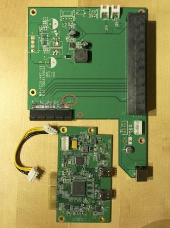
-
Okay. I am a new here so I thought maybe there are some instructions how to put a guide here. I take a look some others what benchmarks they have made, and will modify the earlier post some day, list the parts included etc... Thanks!
-
US$189 AKiTiO Thunder2 PCIe Box (16Gbps-TB2)
euqlaog replied to Tech Inferno Fan's topic in Enclosures and Adapters
Ok, I misunderstood it. 4-pin yellow/black cable has to be in place even if using a normal powered x16 PCIe riser and without barrel plug. Otherwise GPU is never detected in device manager. Continuity tests also showed that there is a very short signal going through to the 2nd PCIe pin from near the tests points of DC jack(when testing without TB card), but not straight 12V line. Therefore I think that PCIe board has a bigger role and we cannot bypass it. But I may be wrong. I could play a little more with the multimeter if I know what to do... -
US$189 AKiTiO Thunder2 PCIe Box (16Gbps-TB2)
euqlaog replied to Tech Inferno Fan's topic in Enclosures and Adapters
Interesting idea. There still can be a power limiting fuse somewhere after the "x4" edge slot however. Assuming that it is also electrically x4, is there any risk to break some components when feeding too much amperes to the slot Tech Inferno Fan? One drawback would be that the TB card is loose and more cables, but maybe they fit inside the enclosure. -
US$189 AKiTiO Thunder2 PCIe Box (16Gbps-TB2)
euqlaog replied to Tech Inferno Fan's topic in Enclosures and Adapters
Only a few GPUs are just plug and play with internal retina screen (Optimus), most of them don't work even if using external screen. Internal screen also has performance loss and I think that your card is too old anyway. I chose EVGA, because people here have had success with Sonnet enclosures earlier. It would be very helpful if people who own MacBook Pro mid 2014 or late 2013 (13" or 15") and AKiTiO's box, would post their results. -
US$189 AKiTiO Thunder2 PCIe Box (16Gbps-TB2)
euqlaog replied to Tech Inferno Fan's topic in Enclosures and Adapters
I refer to Tech Inferno Fan's answer http://forum.techinferno.com/diy-e-gpu-projects/7205-us%24225-akitio-thunder2-pcie-box-2.html#post98895. Some GPUs do work with a standard Windows 8.1 Boot Camp installation. Unfortunately don't know about GTX 580. For OSX you need modified kexts, but I have not yet succeeded with that (external screen is black, however GTX 780 shows up under system report). -
Performance loss is not a problem with a MacBook Pro 15" 2.2Ghz base clock speed, because it is quad-core i7. Your 13" is dual-core, so there is a performance drop and I guess you cannot play for example BF4 (uses a lot of CPU) very smoothly with the retina display, but external may help. With 15" it is smooth with retina as well (not native resolution however) as I am using EVGA GTX 780 6GB SC. All the demanding tasks are done by the GPU.
-
US$189 AKiTiO Thunder2 PCIe Box (16Gbps-TB2)
euqlaog replied to Tech Inferno Fan's topic in Enclosures and Adapters
340.52 driver, downloaded from Drivers | GeForce. -
US$189 AKiTiO Thunder2 PCIe Box (16Gbps-TB2)
euqlaog replied to Tech Inferno Fan's topic in Enclosures and Adapters
I did some additional tests yesterday and if I remember correctly, I wasn't able to get 0.36V again from the 2nd PCIe pin, the first 1-3 pins showed very small voltage (0.05V) when the black probe was on the screwhole (GND). Other pins were 0V (up to 11 pin). The same result, when TB card and its little cable removed. Only when thunderbolt cable was attached to the MacBook Pro, PCIe 2pin voltage was 12V and 750Ti's fans started to spin. When the system was shut down, I also did continuity tests from the screw hole to the PCIe GND pins, and it gave a beep sound. A very short beep sounds occasionally when touching 2nd PCie pin and from the both sides of C2, switching probes place (black/red) resulted a short beep sound again. -
US$189 AKiTiO Thunder2 PCIe Box (16Gbps-TB2)
euqlaog replied to Tech Inferno Fan's topic in Enclosures and Adapters
By the way, I did continuity test from the screw hole (black probe) to the C2 lower part (red probe), and multimeter gave a continuous beep, so that is ground and means good news for us? -
US$189 AKiTiO Thunder2 PCIe Box (16Gbps-TB2)
euqlaog replied to Tech Inferno Fan's topic in Enclosures and Adapters
Tech Inferno Fan can give answers, because my knowledge of electronics is very basic. I am very interested in the 25W PCIe limit existence. Some GPUs apparently need 75W from the x16 PCIe slot, I was lucky with EVGA GTX 780 and Gigabyte 750Ti. -
US$189 AKiTiO Thunder2 PCIe Box (16Gbps-TB2)
euqlaog replied to Tech Inferno Fan's topic in Enclosures and Adapters
I got the following results by using the original 12V/5A power adapter only and PCIe riser half way plugged + black probe on the screw hole, without thunderbolt card, without graphics card: test point -> voltage C3 -> 12.3V left side, 0V right side C2 -> 0V lower, 12.3V upper C4 -> 12.3V lower, 0V upper J6 -> from down to up 0V, 0V, 12.3V, 12.3V 2nd PCIe pin -> 0.36V That -1V offset value was less earlier, got -0.7 and -0.8 readings and it looked like to grow, and the other 11V changed respectively. I think this is the point where I stop my multimeter testing, because I don't want to blow up my board It is still working properly, Optimus enabled.

