
H658tu
-
Posts
107 -
Joined
-
Days Won
3
Content Type
Profiles
Forums
Downloads
Posts posted by H658tu
-
-
It's an Aptio, so use MMTool (or UEFITool), both work with this bios.
Not sure where that limit is coming from, but have you tried ThrottleStop yet? It's much, much better than XTU (which you can ditch wholesale for TS) and has a feature 'Limit reasons' which'll tell you if it is indeed a bios-set TDP limit or, perhaps, an adapter or motherboard current limit.
-
On July 07, 2016 at 4:07 PM, andrewff2 said:
Hey man thanks for the help!!!!
Now i am thinking i how to flash cause as Khenglish stated
" If you don't have a backup image I'm pretty sure you're screwed. BIOS updates that are downloaded are not runnable. They don't have NVRAM configured properly, so a functional NVRAM must already be in place."
And well i was using premabiosmod so i don´t know if i just dl the file and try to flash in programmer will work
It's certainly possible, but never had that particular problem with Clevo bioses.
Only thing you have to be aware of is that the me+bios file is appended end-to-end in a single file ('P375SM03.PM2', 6MB) and it has to be written to two eeproms (2 + 4 MB), so you have to separate them first before using the programmer. Hex editor or something has always worked fine for me, at least for the stock bioses, but don't think Prema's mods are any different at this point.
Search for 'ITE Tech' or navigate to the right hex offset:
Spoiler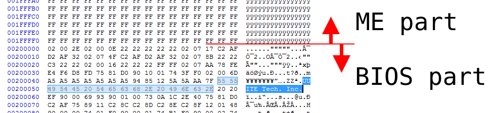
A final check is making sure the byte size matches: 32 Mbit bios eeprom -> 32/8 (=MB) * 1024 (=kB) * 1024 (=B) = 4,194,304 bytes. Same thing for the ME eeprom.
The EC files are smaller than their eeproms since they're not padded like the ME and bios, but after a regular flash it simply leaves the rest of the eeprom blank (FF's), so these don't need additional steps.
-
As it happens, yes. It's for the SM-A version, but it should be pretty similar.
Clevo P375SM-A - motherboard, top view:
Spoiler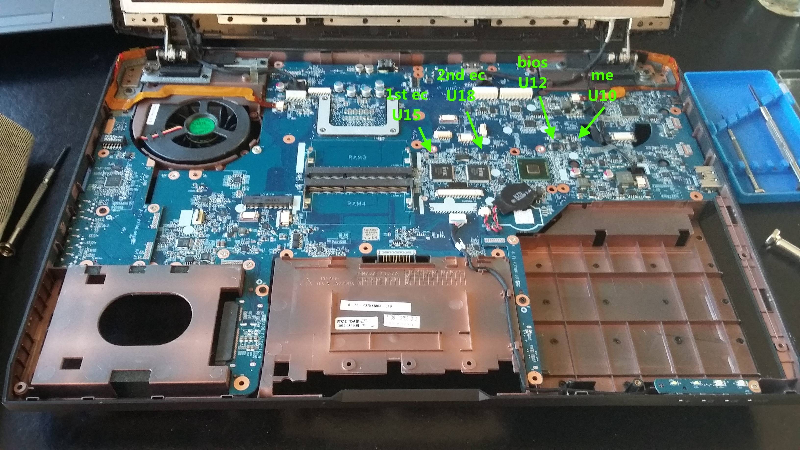
Clevo P375SM-A - BIOS and ME, U12 and U10:
Spoiler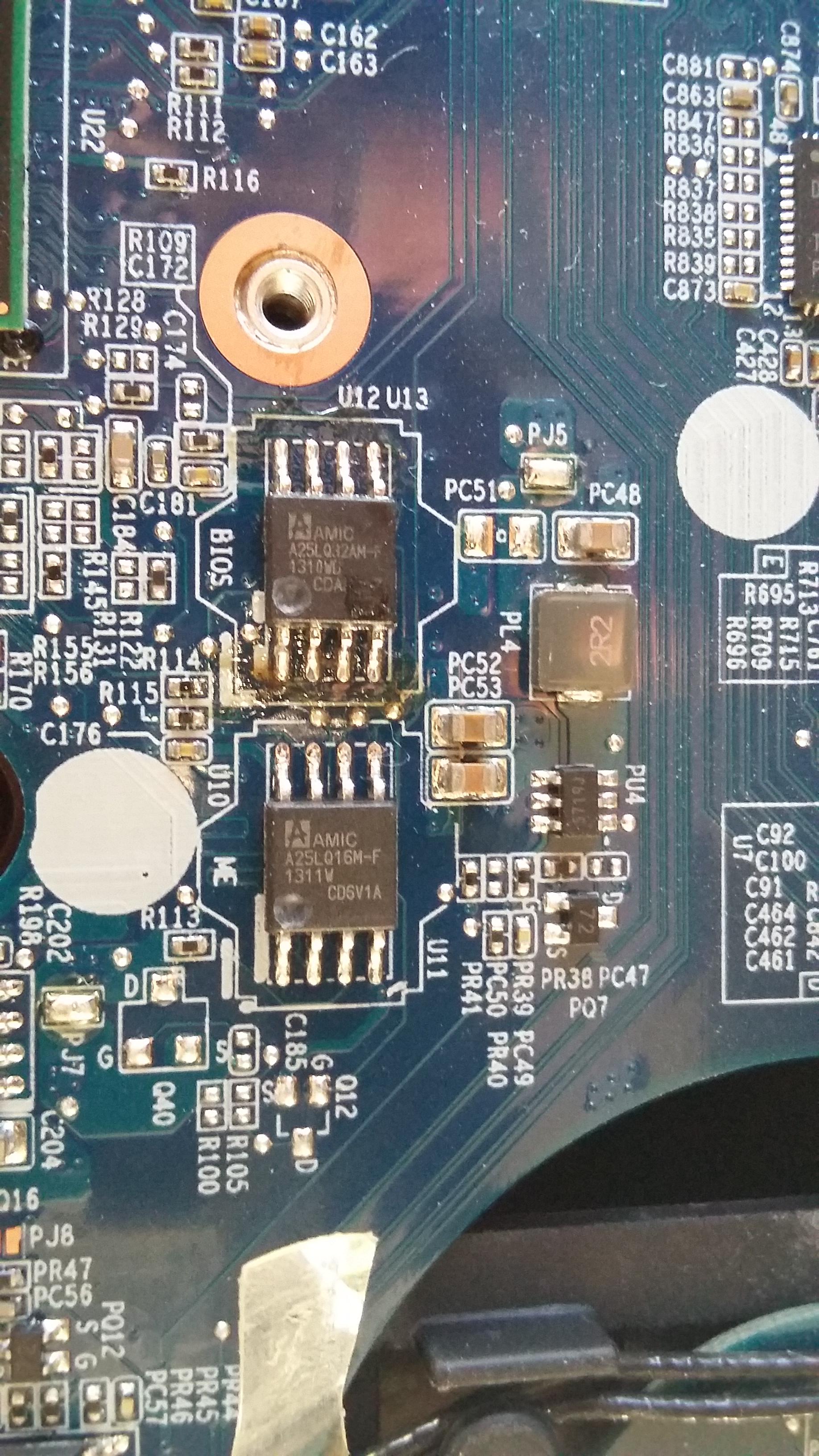
Clevo P375SM-A - 1st EC, U15 (unsoldered already):
Spoiler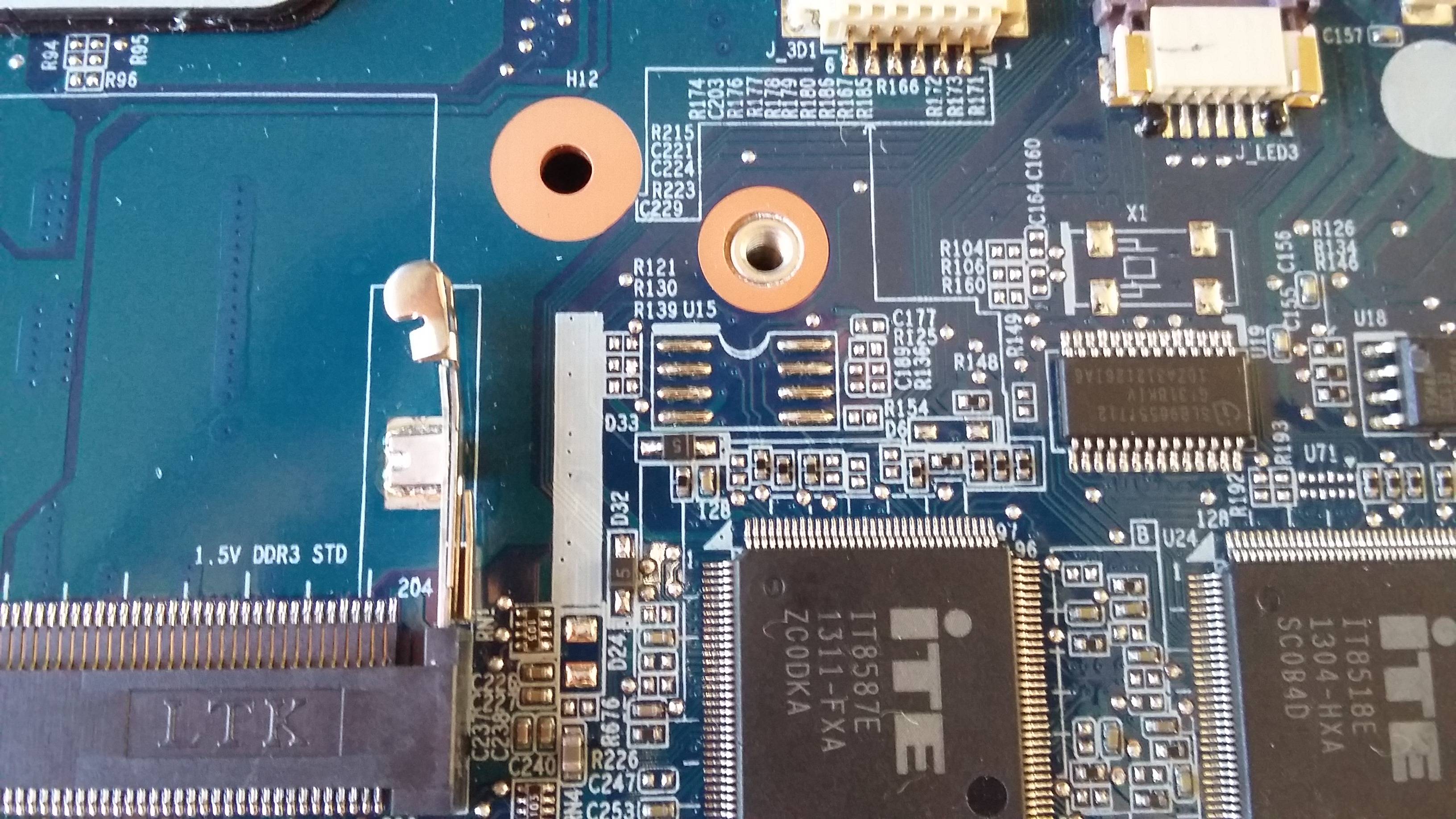
Clevo P375SM-A - 2nd EC, U18 (Pm25LD010):
Spoiler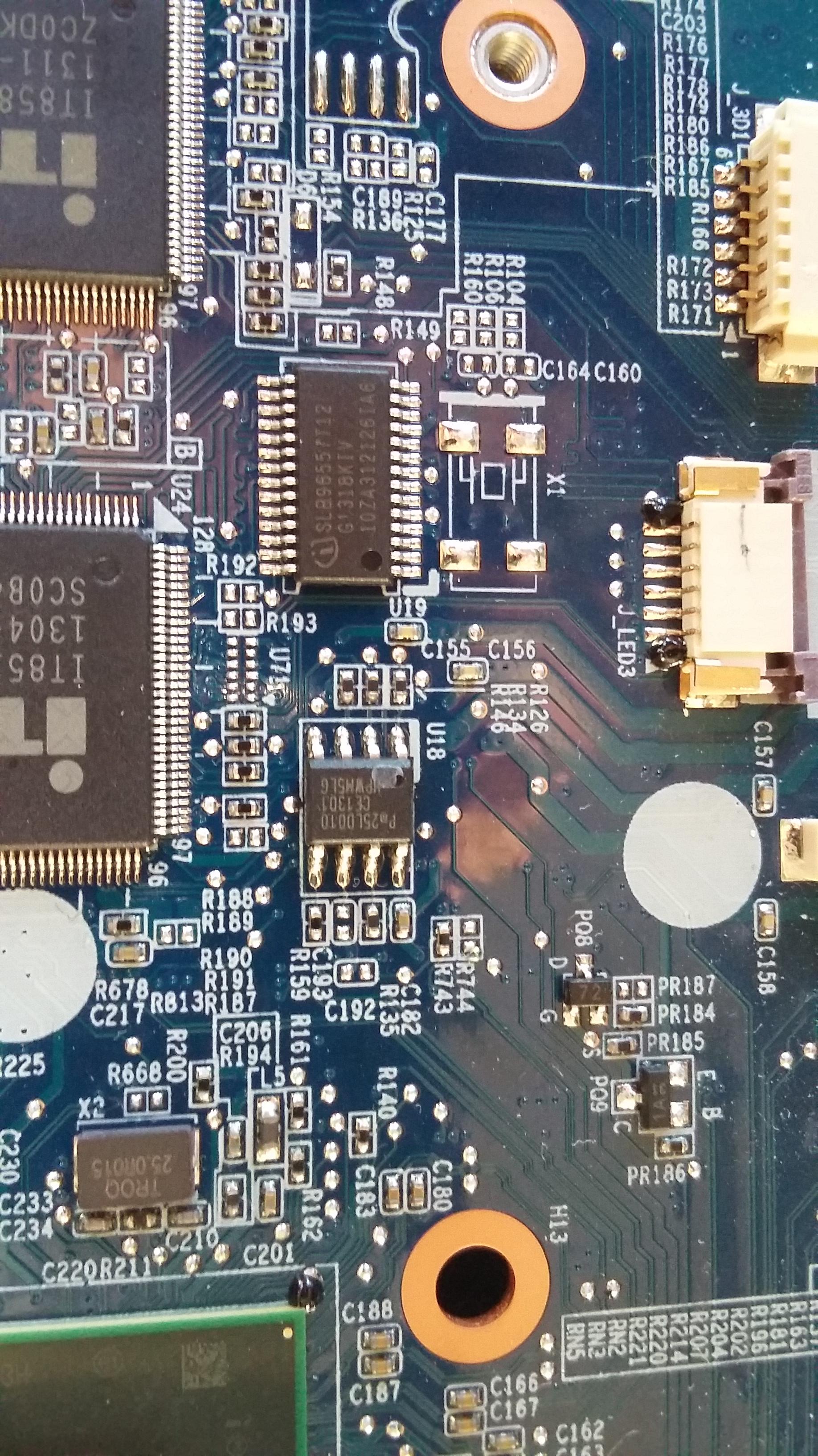
Interesting adapter, btw, hadn't seen that one before. Arm and a leg, though ... currently use these 200 mil adapters, going for $0.30 each, so ~33x cheaper. Unfortunately, form the looks of it your adapter is ~200 mil as well, so neither of them will work for the 150 mil ECs (or a vbios). Looks like they'll do fine for the BIOS and ME; the adapter appears to have a very compact design, so not a lot of additional space is required beyond the eeprom footprint.
Solved the issue for the vbios with some (ugly) trickery and a 200mil eeprom, but it'd have been better if the pads of the adapter extended more towards the centre of the chip, that way they'd work easily for the 150 mils as well.
HD 8970M, socketed vbios:
-
 1
1
-
-
1. The eeproms are the bios and chip you've de- and re-soldered. The binaries are the files I've uploaded before, these should match the files you get when using the 'read' option of the programmer tool after you've written the binaries to them. A hex editor such as HxD has a 'file compare' option for this.
2. Ok.
3. Yes, by measuring resistance (ohms) between the pad on the mb and the top part of the eeprom's pin that should connect with that pad. All eight have to measure zero ohms (~0.001). Well ... technically not all are in use, but it is better to have them all connected properly.
-
Rather odd the new fan isn't working properly, but yes, the blades will come off. They lift a bit, then seem to snag. That's due to the seals which keeps it from detaching and prevents dust/dirt from getting in the bearings. Look underneath the sticker; there should be a plastic O-ring which keeps the blades in place. Pry it loose and the blade section will detach more easily.
-
Three-wire fan shouldn't give any problems, provided the voltage (5V or 12V) matches and its rpm is in the same range as the original (used by the EC for the temp. -> rpm lookup table. Since the original issue is about noise; remove the plastic blades of the old fan, drop some grease in the bearings and it'll run silent again.
-
Check the following:
- Verify the eeproms by reading them with programmer, they should match 1:1 with the binaries.
- Orientation of the chips?
- Measure each pin with a multimeter.
-
That schematic listed by andrzejz78 is a 4-lane connector (TX0+TX1+TX2+TX3 = 4 lanes), so 4k can work, provided you have an eDP-type motherboard plus a 4-lane cable as well (not 2-lane, which is sufficient for 1080p). Voltage is good, too, so the B173ZAN01.0 (4k, high gamut) should be a perfect match. So ... check whether the current panel is eDP and look to see if the cable's pins 1-12 are all populated; if half are missing then you'd need to source another cable.
-
A few weeks ago there was a new bios version released which includes a microcode update for this cpu series:
Spoiler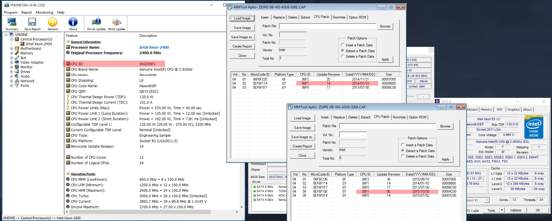
Hopefully that actually fixes the issue ...
-
A cheap usb thingy usually works fine, but something like this will practically guarantee it's compatible with the specific chip you want to program. Each has its own parameters and the hardware+software needs to be aware of that. Same thing applies to the bios flash programs, such as afudos, insydeflash and the like; they have a tiny database listing various eeproms' properties.
Insydeflash's battery check might be overridden by changing the corresponding section of its platform.ini file (or whichever name was used for the .ini):
[AC_Adapter]
Flag=1
BatteryCheck=1
BatteryBound=10
;This flag is the switch of checking AC.
;Flag              default : 1.
;                        0 : Don't check AC.
;                        1 : Check AC.
;BatteryCheck      default : 0.
;                        0 : Don't check battery.
;                        1 : Check battery.
;BatteryBound      default : 20.
;          Integer (1~100) : Low battery boundary (percentage).
;                            When BatteryCheck=1 this value will be referenced.
;                            And only when the battery life percentage is bigger then
;                              inputed value, it can do flash.
edit:
Ah, and you want a SOIC8 to DIP8 adapter to go with the programmer. That will save soldering and de-soldering to the SOIC8 pcb that came with the programmer:
-
1
-
-
Well, then you may as well desolder both bios and ec eeprom and flash them with A11 using a programmer. Might also send them to me. Easy enough and they'll fit in an envelope, so shipping would cost little.
What was the reason for A11, btw? Presumably Dell killed something or another with the newer versions?
-
1
-
-
Was the 25Q64FVSIG pre-programmed ($25) or blank ($2)? If blank then you'd have to program it yourself before soldering. If it already had a bios programmed, then the bios version may have to match the EC version to be compatible. Also make sure to measure all eight soldering joints with a multimeter.
And yes, it's possible that the blind-flash corrupted the EC instead of the bios, provided the switch you've used took that into account. Remember that the file-to-flash as supplied is both bios+ec in one; the ' M14x R2 - A14 bios and ec ' file I've linked earlier has them separated, only these can be flashed directly to the eeprom chip. Flashing the bin as downloaded from the Dell site is futile.
-
Ribbon cables are generic, just get one with the same pin count and pitch (~$2 at most; example). Make sure to have the exposed ends up or down, whatever this specific motherboard connector uses. Next, cut off a section of a credit card to the same width and 1/2" length and jam it along with the cable end, on its non-exposed side, into the connector.
This accomplishes the exact same thing the original did, except a lot cheaper; it's 'only' around $8, but considering it's really a $0.00001 piece of plastic ... thus quite expensive, not to mention principles and such.
-
No need buy a pre-flashed eeprom for $25; the one in your 7970m is fine, it just needs the right vbios flashed to it. Either get a programmer or send me the de-soldered chip, will flash the vbios you want and ship it back. Should be no more than $3 for envelope shipping both ways.
-
Right, there's two alternatives:
1. Flash on an SLI/CF (m18x, say) or optimus/enduro system. Since the vbios should be fine aside from the undervolt, then either system will boot without problems; one on the other gpu and the optimus/enduro using the igpu.
2. Force flash. Chance of success is small, considering the blinking leds; most likely indicating failure in the power-up sequence. Anyway, copy this in the root and replace newrom.rom with your own: autoflash ati.
It's just a few simple switches in the autoexec.bat, plus a very useful beep.bat which, of course, makes the procedure beep at the right time, indicating 'booted from usb' and 'flash finished'.
-
On Saturday, January 09, 2016 at 11:30 AM, Blackyhimself said:
which chip is the bios chip?
Spoiler
There's a dot 'depression' on the eeprom and an arrow or 'dented' rectangle on the pcb, these identify pin #1 and, thus, indicate the correct orientation of the chip. Both are present in the image; bottom-left corner of the eeprom. Remember to use use a multimeter after re-soldering in order to verify all pins have a proper connection.
-
It's there, as well:

Perhaps the mod allows you to disable it in the bios menu? Depends on whether that option is (still) hidden or not. Not sure Prema can actually do something about this without running into lawyers and such; it's Clevo's decision to implement this anti-theft 'technology' <- rootkit, certainly, would be a better term.
-
That's fine, just means the bios doesn't have those included (optional roms). Everything else looks good, too.
Check bios options for 'extended boot' or some-such and, if you're using Windows 10, disable Fast Startup. Also check boot order, just in case it attempts network boot before hdd/ssd.
-
22 hours ago, freddy24 said:
I will do it and please i wiill write here more till my bios is flashed, please can you visit here more days so i can find some answer from you!!!!
Sure, if the new forum behaves as expected ...
22 hours ago, freddy24 said:So first i flash the w25q64 chip on location u48 witht he bios bin and then w25q80 chip that is with ec bin file ?
Yes. Make sure to wipe the chip first (zero all bytes) before writing the new firmware. Existing bios has a protecte, read-only portion you want to overwrite as well, this is the best way to make sure that happens.
5 hours ago, edeiel said:Hey. i`m need dump chip u604. Have it ? Sorry for my English)
Yes, it's the 'M14xR2_A14_ec.bin' in the file I've linked earlier.
-
Quote
here is the pic with size of the bin file i have.
Better use my files then; the 'isflashWin.bin' is a packed bios and wouldn't do any good.
Quotecan i reprogram both chips without taking from motherboard and re soldering back
Only ~5% of eeprom chips support this method and then only if the motherboard's wiring matches. So ... don't count on it; solder.
Quoteif i can flashed on the board with claps , them with this tool ?
The clamp is still useful; you place the de-soldered eeprom inside it, then attach the clamp's cable to the blue pcb, which, in turn, can then be placed in the black 'grill' thingy of the programmer.
-
Is that .bin 8MB exactly? That is, 8x1,024x1,024 = 8,388,608 bytes? Otherwise you'd be flashing the wrong file; the programmer expects a 1:1 byte-size match to the eeprom.
Anyway, remembered just now to extract the packed payloads. Here's both A14 bios and ec:M14x R2 - A14 bios and ec (plus the downloaded Dell .exe)
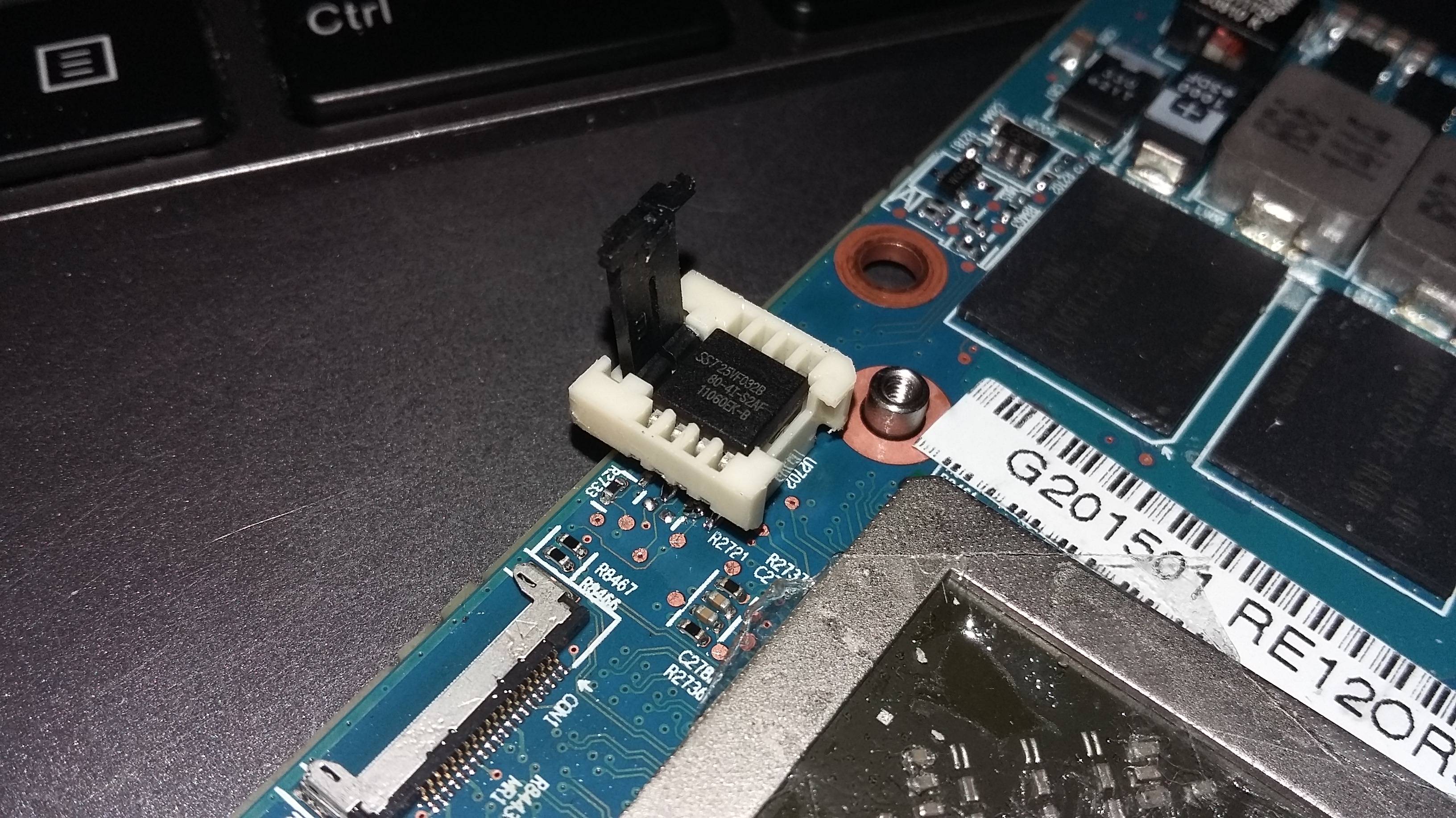
Mind that you use a multimeter to verify the pins make good contact after re-soldering. Set it to Ω and place one connector on the soldering pad and one on the eeprom's pin:
It should measure '0.00' for all eight pins.
-
W25Q64FVSIG contains the bios, W25Q80BVSIG (most likely) contains the EC. The 64 and 80 are a dead give-away; 64 = 64Mbit/8MB and 80 = 8Mbit/1MB (don't ask ...). You'll want to try the bios first and, failing that, the ec.
A problem you may run into is that Dell supplies packed bioses, not plain binaries. The 'isflashWin.bin' is 9.44MB, so there's an 8MB bios + 1MB EC inside (plus some fluff). It isn't difficult to separate them, since they trail side-by-side after the header. Only thing; forgot how and my notes are on a different system, either wait till tomorrow or google-fu yourself.
-
$10 ≠ 'earning money', it is a small tip.
-
1
-
-
€125 is crazy, €25-35 is fair; takes no more that 15-30 minutes. Could do it for you if they don't want to budge, just pay return shipping and we're good (€9). Can't test it in a Medion, but have a non-enduro Clevo, so that should work.
And you need to be 'Promoted' to download stuff, see this message for info. Anyway, no need for that; the v019 in the link is an older version, so you might as well flash the v21/P370EM from the TPU site.
Using eGPU with lid closed in Windows 10
in Apple eGPU discussion
Posted · Edited by H658tu
Apart from the restart, you could also remove the magnet from behind the display bezel. This triggers the reed-switch that tells the system 'display = closed'. Of course, the backlight would remain on (and draw a little power), but at least there'll be no more shenanigans with any software, regardless os, as to what 'consumer-friendly' power saving features to use when there's no internal screen in a view-able position.