


bg6dt
-
Posts
7 -
Joined
-
Last visited
-
Days Won
2
Content Type
Profiles
Forums
Downloads
Posts posted by bg6dt
-
-
On 10/15/2019 at 9:47 AM, invait53 said:
Okay but can you show here the former of printed circuit board with both sides and with real size and holes? I will order it by myself.
I designed it using kicad software. If you can use this software, I will send you the PCB layout file.
-
16 hours ago, adrian_sa said:
@bg6dt Thanks for the tip, got the backlight working and also applied the VBT mod. What did you do to the IntelIvbGop and IntelSnbGop drivers? Is this from a another machine?
That's great. I am very happy that this is helpful to you. You mean IntelIvbGop and IntelS nbGop drivers?I replaced the new driver with the UBU tool(UBU_v1.71.1).
I am curious to know how your backlight works, panel enable signal and the pwm signal.
-
On 10/10/2019 at 10:41 PM, invait53 said:
@bg6dt Well done. Can you do that plates more and sell it? Very interesting mod.
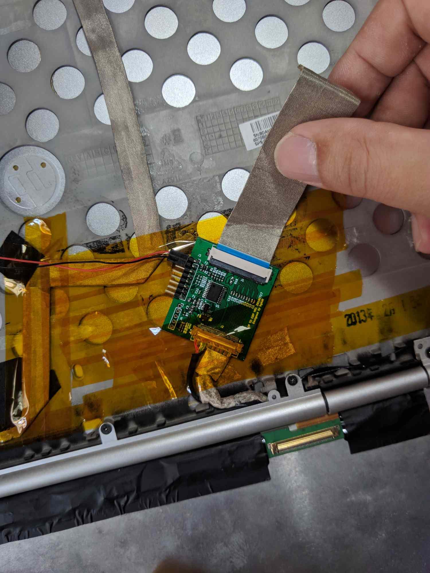
I've found on Ebay LVDS to eDP converter. Very simple to install.
I am not a businessman, doing this is just my interest, so I am not ready to sell these.
The 2570p has only a single LVDS signal, and the resolution cannot be used above 1440x900. If 1440x900 or more is required, a dual LVDS signal is required.
-
On 10/6/2019 at 4:22 PM, invait53 said:
Good job, show schematic pls.
Backlight enable detection, I used the voltage detection of Lane0_P, when the EDP has a signal, the voltage is 0.5V, when the EDP has no signal, the voltage is 0V, MCU uses ADC detection, output high and low level signal control panel backlight.
Backlight brightness PWM, MCU detects keyboard FN+F9 and FN+F10 buttons, output PWM signal control panel brightness .
Modify BIOS VBT, modify with Intel BMP Utility tool, delete internal LVDS display, do not use clone mode, only one monitor, full UEFI mode works perfectly, external monitor works perfectly. The BIOS version I use is F.72, see VBT.ZIP file.
2K panel model: LQ125T1JX03C
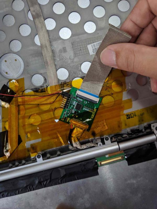
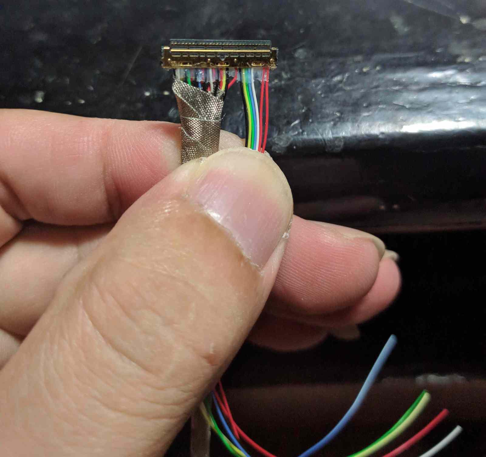
Edp signal cable, I made it myself, the signal cable length is 13cm, the differential signal cable is twisted and twisted, covered with shielding tape.

-
 2
2
-
-
On 10/8/2019 at 4:09 PM, MioIV said:
Hello, how do you found that? Did you edited IFR section (or replaced from 8*70 PS module)? I see a lot of changes. Am i right that WWAN-device will be inaccessible then? I've noticed that Bluetooth option after removing according module didn't affect anything thought, maybe with WWAN will be same story.
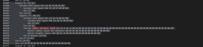
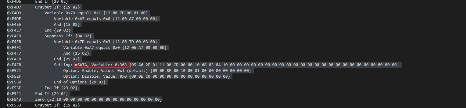
Yes, what you said is correct. I compared the BIOS of 8770W. after edited the IFR section, the key point is this: Variable: 0x368, and I have deleted the WWAN module using UEFITool. I plugged the bluetooth device into the WWAN socket, bluetooth Work perfectly, no whitelisting problem.
-
2
-
-
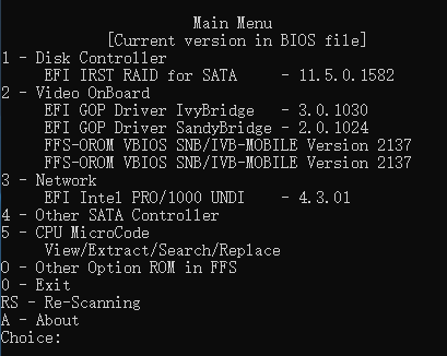
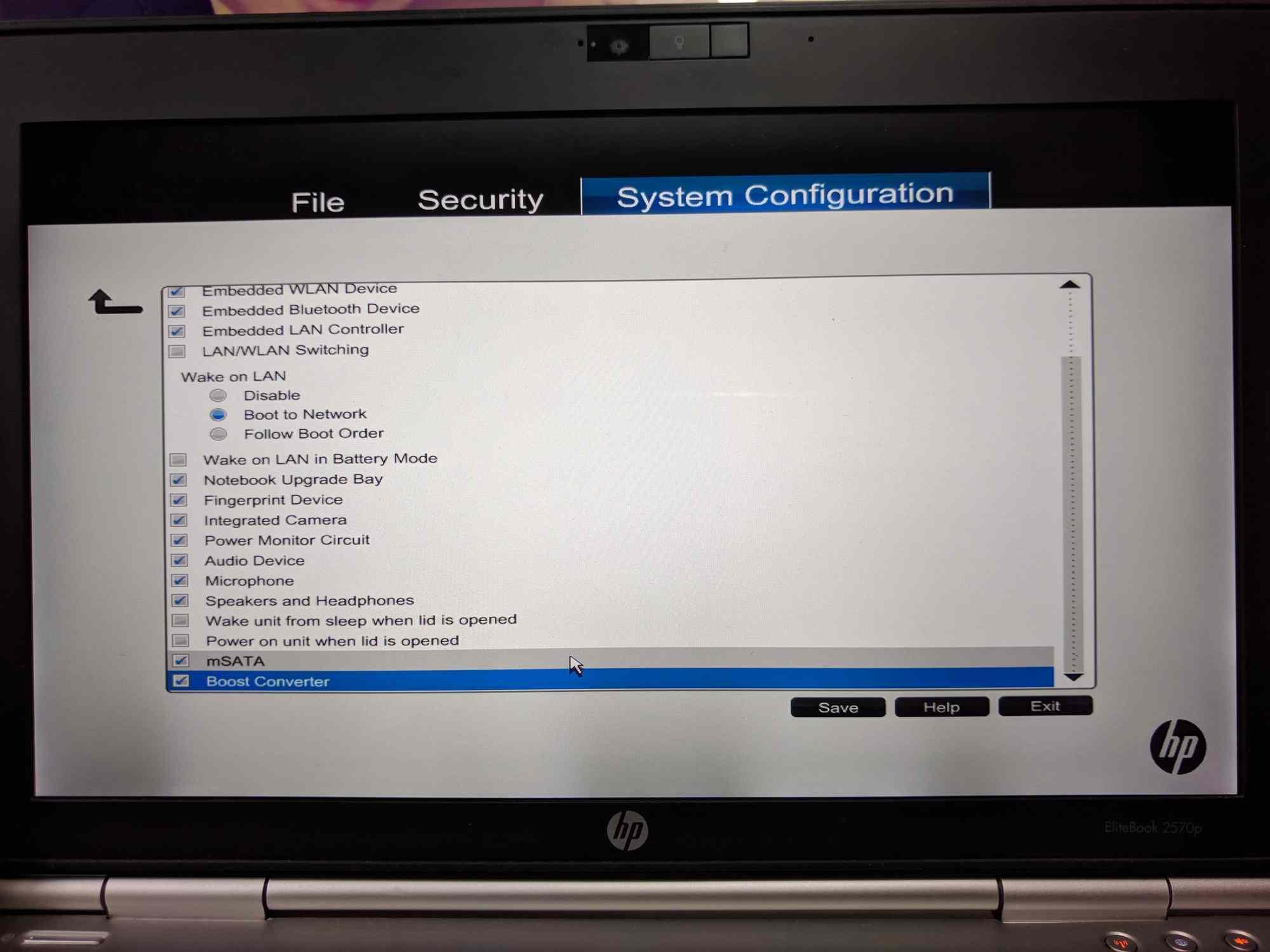
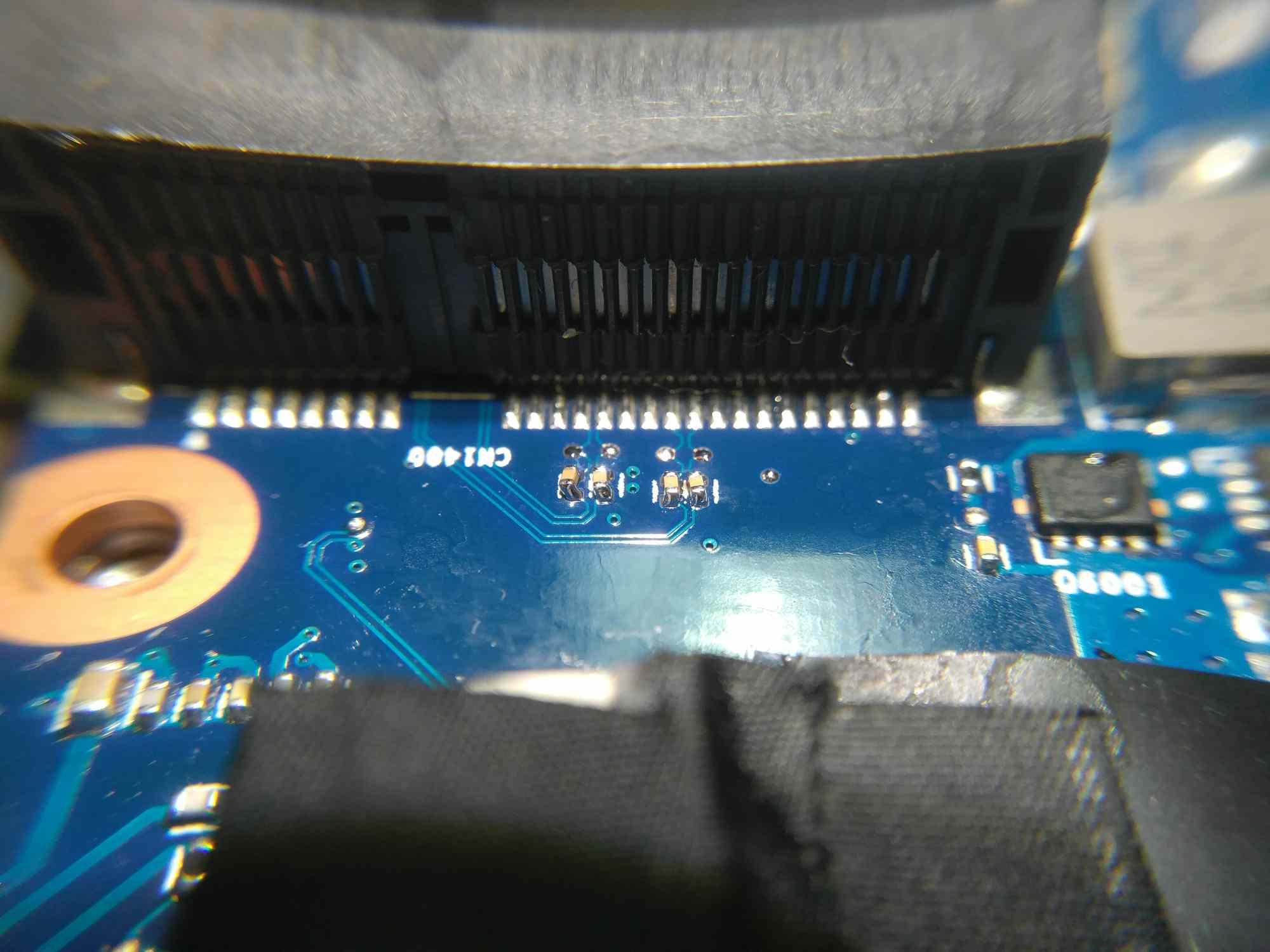
Hi, guys, please forgive my english is every poor, I hope you can understand what I said. about msata, I delete the BIOS's SecureUpdating module and modified PlatformSetup module, removed the modem option, added the msata option, msata works perfectly, but can't boot the system directly from msata. The BIOS version I use is F.72, modified with the UEFITool tool, if you are interested, you can test it, but you must be careful, you must know how to use UEFITool and flash BIOS. It is important to backup your original BIOS before you start.
The motherboard's WWAN socket sata line needs to solder four 0.1UF capacitors or 0 ohm resistors.
I also changed the TFT to 2K display, using the DP in the docking station's interface.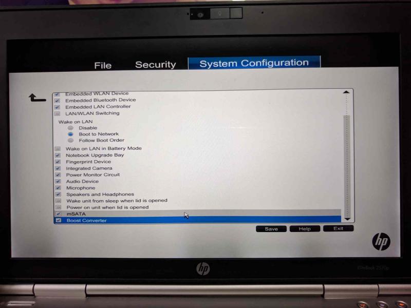

-
1
-
12.5" HP Elitebook 2570P Owner's Lounge
in HP Business Class Notebooks
Posted
DP_TO_EDP.zip