adrian_sa
-
Posts
18 -
Joined
-
Last visited
-
Days Won
8
adrian_sa's Achievements
Settling In (2/7)
20
Reputation
-
12.5" HP Elitebook 2570P Owner's Lounge
adrian_sa replied to Tech Inferno Fan's topic in HP Business Class Notebooks
Well its working good when not charging, when charging the screen begins to flicker. The wire is probably too long so it picks up interference. -
12.5" HP Elitebook 2570P Owner's Lounge
adrian_sa replied to Tech Inferno Fan's topic in HP Business Class Notebooks
@bg6dt Thanks for the tip, got the backlight working and also applied the VBT mod. What did you do to the IntelIvbGop and IntelSnbGop drivers? Is this from a another machine? -
12.5" HP Elitebook 2570P Owner's Lounge
adrian_sa replied to Tech Inferno Fan's topic in HP Business Class Notebooks
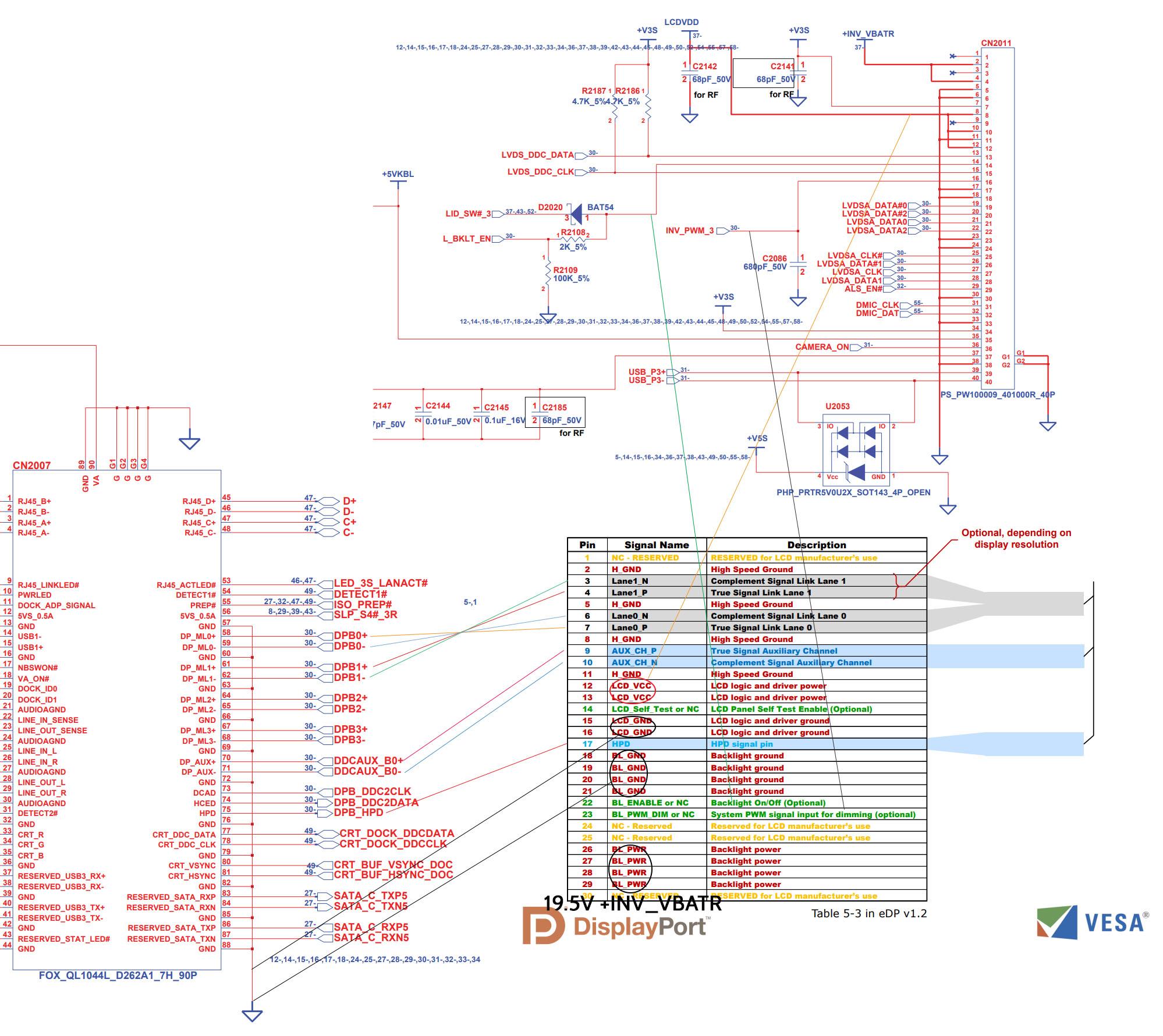
I used the wire that I linked on aliexpress, just cut off the connector and solder the wires directly. I can see the BIOS, posted also about that, the BIOS doesn't work in full UEFI boot mode but if you switch to hybrid it does work. I also modded the VBT so I can use clone mode for the display. Right now I can you only the internal display or an external display via DP or VGA. I can't use extend mode. I dont know if 4 lines would work with this basic method, 1080p uses RDR(reduced data rate), for 2k you need HBR so there is bigger concerns about signal integrity. The next step would be to implement MCU which would take care of the backlight control, but I don't where to get the Backlight enable pin if I disable the LVDS interface. The HPD pin is always high when machine is on. The Chinese x230 FHD mod uses USB with software I suppose to control the backlight. -
12.5" HP Elitebook 2570P Owner's Lounge
adrian_sa replied to Tech Inferno Fan's topic in HP Business Class Notebooks
@invait53 eDP and DP are compatible, you can buy the cable I linked a few pages ago and solder it directly to the board, The vias are exposed near the dock connector under the heatsink.
-
12.5" HP Elitebook 2570P Owner's Lounge
adrian_sa replied to Tech Inferno Fan's topic in HP Business Class Notebooks
@invait53 Sorry, I was busy using the notebook in the field So far the mod holds up. I soldered the pairs to the dock connectors, there are vias on the board from which you can scrape off the solder mask and solder the pairs. Also you need HPD and I soldered the backlight enable and PWM pins to the pins of the old LVDS display. To do the VBT mods download the UEFITool and search for $VBT in non-unicode, you will find three modules, extract their bodies and open the files with Intel BMP, you can find the tool in the winraid forum. Now its been a while and I dont remember all the changes I did, I will have to find the bin file and share it here so you can compare. My method is flawed because right now I cant use a third monitor, the old LVDS interface is still working because of the backlight part, I will have to disable the LVDS and add a Arduino to control the backlight instead. I think that the HPD pin goes low when the display goes to sleep so I could probably use that. -
12.5" HP Elitebook 2570P Owner's Lounge
adrian_sa replied to Tech Inferno Fan's topic in HP Business Class Notebooks
Well I'm using it on a daily basis and I slam sometimes the lid and no problems. I think that the cable will fail first, I grinded some parts from the lid because the electronics of the panel whre interfering but this could be done without grinding with the right panel. I had this one on hand so I used it @invait53 Yes the webcam works. -
12.5" HP Elitebook 2570P Owner's Lounge
adrian_sa replied to Tech Inferno Fan's topic in HP Business Class Notebooks
At last success I took the VBT boot screen table from the X230 and also set the boot mode to UEFI with CSM, pure UEFI doesn't work for some reason. I also changed the default LVDS resolution to 1080p and also the BL PWM frequency to 2000Hz. The display works in clone mode now. -
12.5" HP Elitebook 2570P Owner's Lounge
adrian_sa replied to Tech Inferno Fan's topic in HP Business Class Notebooks
Mine monitor is also 1440p but I think that the VGA and HDMI outputs are limited to max 1920*1200p60. I will try disabling LVDS because the BIOS recognizes my monitor but it doesn't display anything, maybe one on the pipes are used by LVDS. -
12.5" HP Elitebook 2570P Owner's Lounge
adrian_sa replied to Tech Inferno Fan's topic in HP Business Class Notebooks
Done some VBT modding today, I can now get the BIOS screen via VGA and HDMI always. The added eDP panel that's connected to the dock still shows no boot screen and there is no picture output via the DP port. I will try disabling the LVDS tomorrow. -
12.5" HP Elitebook 2570P Owner's Lounge
adrian_sa replied to Tech Inferno Fan's topic in HP Business Class Notebooks
On the right side top side, the 3 hotkeys. -
12.5" HP Elitebook 2570P Owner's Lounge
adrian_sa replied to Tech Inferno Fan's topic in HP Business Class Notebooks
I cleaned up the wiring and modified the lid so the panel fits now but it's still a bit to tall. Brightness control works good. I also tried compiling Coreboot but I'm getting just a blank screen, I will try to fiddle a bit with the video settings. -
12.5" HP Elitebook 2570P Owner's Lounge
adrian_sa replied to Tech Inferno Fan's topic in HP Business Class Notebooks
I got a i7-3630QM but only 4GB RAM and the stock 500GB HDD. I will certainly update to 8 or 16GB later down the road, for now I'm concentrating on the hardware mods. The panel I used is a BOE NV125FHM-N62, but I used just because I had it laying around from my ThinkPad X250 which I upgraded to 13.3". http://www.panelook.com/sizmodlist.php?st=&pl=&sizes[]=1250&resolution_pixels=8180 Here is a list of 1080p panels that could fit probably, you still have to double check the dimensions. https://s.click.aliexpress.com/e/bGMJQ8aM This is the cable I used, I cut the header and soldered the high-speed pairs directly to the motherboard. There are via from which you can scrape of the PCB solder mask. I will post a longer explanation later on. Here is picture with a second 1440p DP monitor. The biggest problem currently is that I can't get the BIOS screen to show up on the new display. -
12.5" HP Elitebook 2570P Owner's Lounge
adrian_sa replied to Tech Inferno Fan's topic in HP Business Class Notebooks
This is my 1080p IPS mod, still have a lot to do but most importantly the panel works great. Maybe I should get a panel with a bent PCB so that it fits better. The DisplayPort is rerouted from the docking port to panel via a cable from AliExpress. -
12.5" HP Elitebook 2570P Owner's Lounge
adrian_sa replied to Tech Inferno Fan's topic in HP Business Class Notebooks
No, I messed a few days with BIOS but could enable the SATA lanes. The WWAN whitelist works so you can now use any 3G/4G miniPCIe WWAN module. -
12.5" HP Elitebook 2570P Owner's Lounge
adrian_sa replied to Tech Inferno Fan's topic in HP Business Class Notebooks
Here is the link https://forum.51nb.com/forum.php?mod=viewthread&tid=1751735&mobile=2 The PCIe part could be probably enabled by chainloading Windows. WWAN cards typically use only USB so you can stick a 4G card in it.