

Brian
-
Posts
3678 -
Joined
-
Last visited
-
Days Won
120
Content Type
Profiles
Forums
Downloads
Posts posted by Brian
-
-
Information originally from my Wikia site which is no longer available for use. Thus I have migrated the information to our new forum:
United States
Casing
* Y750M - Dell Alienware m17x Silver LCD Back Cover
* J226N - Dell Alienware m17x Black LCD Back Cover
* Y727M - Dell Alienware m17x Silver Bottom Base Cover Assembly
* J180N - Dell Alienware m17x Black Bottom Base Cover Assembly
* J181N - Dell Alienware m17x Red Bottom Base Cover Assembly
* 8MK45 - Center Control Power Button Cover / Hinge Cover
* KGR2D - Touchpad/Palmrest
* C395N - Bottom Cover Assembly
RAM
* W795M - MOD,DIMM,8GB,1333MHZ,DDR3,2X4G
Miscellaneous
* F836R - Alienhead Mousepad
* N329P - Alienware Generic Nameplate
Alienware m17x
Motherboard
* F415N - Dell Alienware m17x Laptop Motherboard (System Mainboard)
* F421N - Dell Alienware m17x Mulitmedia Audio Ports USB IO Circuit Board
Alienware M17x-R1
CPU
* D720P - Module, Processor, Core Penryn QX9300, ANW NBK
GPU
* D684N - ATI RADEON MOBILITY 4870 CFX (DUAL)
Hard Drive
* H375M - Module, Solid State Drive, 256 S2, 2.5, RBAM, Across Line Of Business
* F584N - HDD 1 Caddy Set
o Y248M ASSEMBLY..., BRACKET..., HDD, SECOND..., M17X
o F673N CONNECTOR..., Serial ATA..., 22P, FEMALE..., S, FEMALE..., INTERPOSER
o D837T SCREW..., M3.0.5P, L3, ANW, M17X
* HYT0K - Module, Bracket, HDD, FOAMKIT, M17X
Optical Drive
* Y329J - Module, Dvd+/-rw, Sony Nec Optiarc Inc., BARE, Alienware
Wireless
* C771R - Module, Card, Network, AW1510, United States
* MGNNT - Module, Card, Network, 370, Foxconn, Consumer Notebook, Dell Americas Organization
Keyboard
* Y573P - Module, Keyboard, Alienware United States, England, M17X Dao/bcc
Screen
* K001R - Module, Liquid Crystal Display, 17.0 Wide Ultra Extended Graphics Array, Alienware, M17X
FM Tuner
* YC8XT - Module, Tuner, Software, TVT11 NTSC, Advanced Television System Committee
Battery
* T780J - Module, Battery, Primary, 85WHR 9C, Dynapack International Technology Corp
AC Adapter
* K972H - MODULE..., ADAPTER..., ALTERNATING CURRENT..., 240W/210W, DELTA - AC ADAPT..., WORLD WIDE...
* N971H - MODULE..., CORD..., POWER..., 125V, 2M, C13, UNITED STATES...
Software
* WR9G4 - MODULE..., SOFTWARE..., W7U64, DIGITAL VIDEO DISK DRIVE..., MULTI-LANGUAGE..., ANW
* W871N - Module, Software, WINDOWS-LIVE Consumer
* D9KVP - MODULE..., SOFTWARE..., QUICK FIX ENGINEERING..., WIN7, CNB
* H919R - Module, Media, Resource Dvd, Alienware, M17X
Alienware M17x-R2
Battery
* W075J - Battery, Primary, 85WHR, 9C Lithium, Dynapack InternationalTechnology Corp
* D582J - 9-cell Primary Battery
Keyboard
* 8WK6F - Keyboard, Alienware, 101, ENG-US, Personal Computer
CPU
* G335R - Intel Core i7 820QM
* MM14W - Intel Core i7 940XM
Screen
* K1NFP - 17" Samsung RGBLED (1920x1200) 1200p WUXGA
* 9PHFF - 17.0" UltraSharp WUXGA (1920x1200) 1200p RGBLED Display with TrueLife
Hard Drive
* H608T - 500GB 7200RPM SATA Hard Drive
* H609T - 500GB 7200RPM 2nd SATA Hard Drive
* K256M - Solid State Drive, 256GB, S2 2.5, Samsung, RBAM
* 9JPNY - HD Bracket + Foamkit (should have interposer and screws)
Optical Drive
* TR555 - Dvd+/-Rw, 8X, Serial Ata, SLOT, Sony Nec Optiarc Inc.
* CDKX3 - Slot Load Blu-ray BD-R, BD-RE / DVD+/-RW Drive with DVD+R double
RAM
* X830D - Dual In-Line Memory Module, 4GB1333MHZ, 512X64, 8K, 200
Wireless
* 4W00N - Intel Ultimate N WiFi Link 6300 a/g/n 3x3 MIMO Technology
* K5Y6D - Broadcom BCM94313HMG2L half size mini PCI wireless network card (Quad mode 802.11a/b/g/Draft-N)
* M960G - Bluetooth Module
Video Cards
* ATI Radeon 5870 Mobility
o F603N - Left Fan
o F605N - Right Fan
o C8245 - 5870, primary - (goes on left side)
o RV546 - 5870, secondary with cable and heatsinks (goes on right side)
* NVidia® GeForce® GTX 285M
o F2T8J - SLI Dual 1GB GDDR3 NVIDIA® GeForce® GTX 285M
AC Adapter
* J938H - 240W AC Adapter
* 5120P - Cord, Power, 125V, 6Feet, SJT..., Unshielded
Documentation
* WRD6T - User Manual
* DW6RN - Software/etc
-
 1
1
-
-
UPDATE 12/15/09: John from Dell spoke to engineering about this issue and unfortunately the response was a disappointing one. Here is what he posted in the thread:
Hey all. I spoke with engineering last night and early this morning, and wanted to give you an update on what we have.There's been some pretty extensive testing on this issue, and our engineering team has come to the conclusion that throttling shouldn't occur at all in any real world scenario. As a result, they aren't planning on doing any BIOS revisions in response to this, but are still investigating to see if they can discover what causes this behavior while using these testing programs. It is, however, the general consensus that changing this is too risky for the potential payoff… too much could go wrong when this really isn’t a behavior you’d see while gaming.
That being said, this system should scream when gaming, and if you have any performance issues, they probably have nothing to do with this, and you should contact tech support to troubleshoot.
I did ask about folding@home's implications on this, and was pleased to discover several people on our engineering team that use the program. They discovered that folding at home drove the cores to 90% and stopped, and only did this when the system was idle, and therefore shouldn't trigger throttling.
I know this isn't the answer many wanted to hear, but this is where we're at.
From my personal perspective, I'd like to say that if what I'm doing with my system drives my CPU cores and GPU to a sustained 100%, I'd expect performance issues there, and would probably be looking to upgrade my system. I don't see that happening with this system any time in the near future.
This is what my response was and I hope other gamers share my concern and voice their opinion with Dell as well:
It is indeed a disappointing response from the engineering team but you have our thanks for bringing it up with them. I hope they are fully aware that even if some of the AAA title games that have been tested aren't exhibiting the problem right now, a game released tomorrow or in the next 6 months may very well force the CPU to work at or near peak load. When that happens, the GPU will throttle and Dell will have many many angry customers on its hands demanding to know why their expensive gaming system is rendered obsolete.-----------------------------------
Download links for the programs discussed in this thread:
1. Furmark
2. GPU-Z
3. Prime 95
5. HWMonitor (not mentioned but recommended anyway)
6. ThrottleStop used to set a fixed multiplier and disable clock modulation.
7. RivaTuner 2.24c (needed for throttling fix)
-----------------------------------
***DISCLAIMER: I TAKE NO RESPONSIBILITY SHOULD ANY DAMAGE OCCUR TO YOUR SYSTEM. TRY THIS AT YOUR OWN RISK!***
Instructions for testing, please note these are general guidelines only:
-Apps: Furmark, Prime95, GPU-Z (for monitoring), RealTemp (to monitor CPU frequency) and optionally RivaTuner.
-Settings:
-
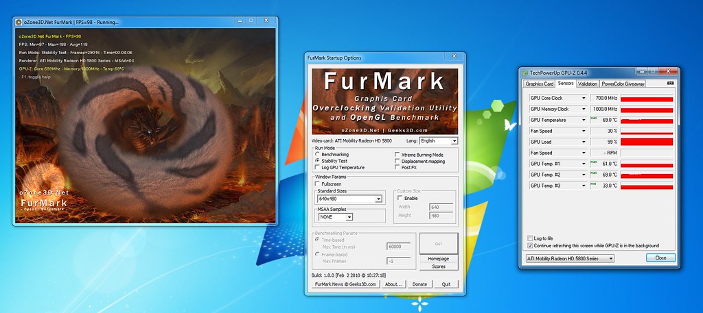
Furmark: Native resolution (for me it's 1600x900), 16xAA, checkmark the stability test box, checkmark the xtreme burn button and also checkmark the post processing button.
-
GPU-Z: Have it open with the sensor tab selected so you can monitor the clock fluctuations in real time. Also checkmark the continous refreshing box + the log to file box so you can reference it later.
-
Prime 95: Small TFTs, 8 threads.
- RealTemp: Use it to measure and log CPU frequency changes (as well as view the active load). Use the logs from this program and compare them to the GPU-Z log.
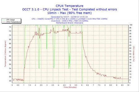
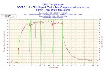
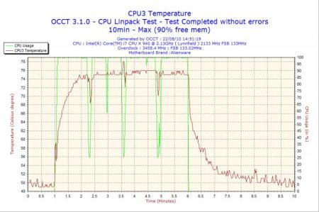
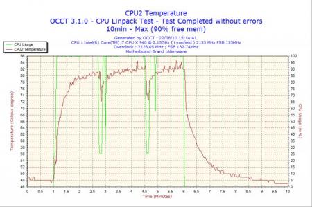
Once you have run the above 4 applications simultaneously at stock GPU clocks, take note if you have seen any fluctuations in GPU clocks (you will see the Furmark graph throttle like how I depicted and your GPU-Z log will also show clock changes). If there are fluctuations, you are likely witnessing throttling. Take note of the RealTemp CPU frequency log and see how it matches up with the GPU-Z log.
EDIT 8/08/10: Although the above method to test for throttling does work when testing for 260M throttling, keep in mind it is an extreme form of testing and may not be reflective of real world use. To gauge if your system is throttling in day to day gaming, it would be advised to try a CPU/GPU intensive game such as Bad Company 2, Grand Theft Auto IV, StarCraft II etc. If you note throttling in those popular games, then Dell needs to be contacted.
-----------------------------------
Background info.:
I've posted this in the main M15x thread but I think this deserves it's own thread since it could be a potentially serious issue with the M15x design. To give some quick background information on the issue with people not familiar with it: The M15x, using stock GPU clocks or when overclocked, will throttle it's speed from the default 575/950/1350 to 3D clocks of 383/301 anytime the system is placed under heavy stress (e.g. this could happen in a game that stresses the system considerably).
-----------------------------------
Original post with some changes:
It seems the M15x is having similar power throttling issues as the Dell Studio XPS 1645. I did a reinstall of the drivers with 186.81/186.82/195.55 (all 3 got the same results) and used the following settings:
Intel burn test: 32 threads, maximum stress level or Prime95 using a maximum of 3200 MB of memory set to custom mode and 8 threads.
Furmark: 1600x900, 8xAA, stability test, post processing and xtreme burn
GPU-Z for monitoring.
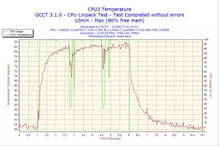
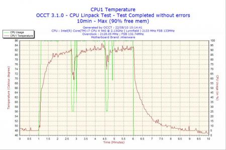
The results will surprise you all:
Overclocked settings: 620/950/1550 with the above settings except furmark was not using post processing (so even less stress was placed on the system):

Notice at the beginning I kept the display brightness to zero to test if this was indeed a power issue. There were no dips in performance (no throttling) when I had it at zero. I then moved the LCD brightness to half and shortly thereafter, the throttling started. I then later moved it to full brightness and a you can see, the rate of cycling from full clock to throttle clocks occurred more frequently. At the end of the graph, I set the brightness back to zero and it was again stable at full clocks.
-----------------------------------
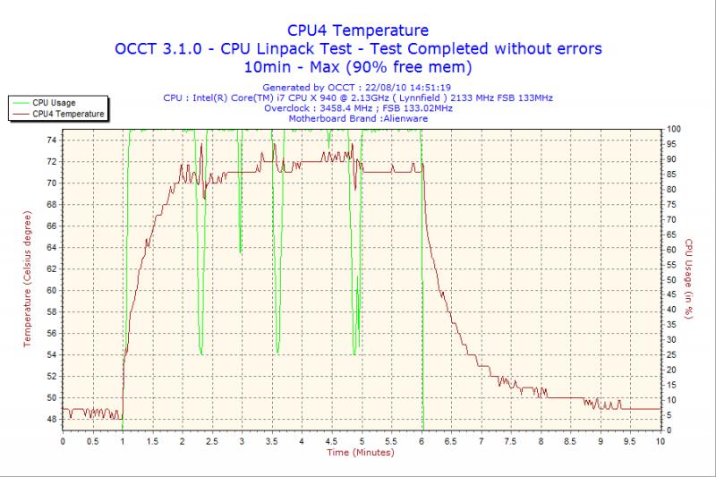
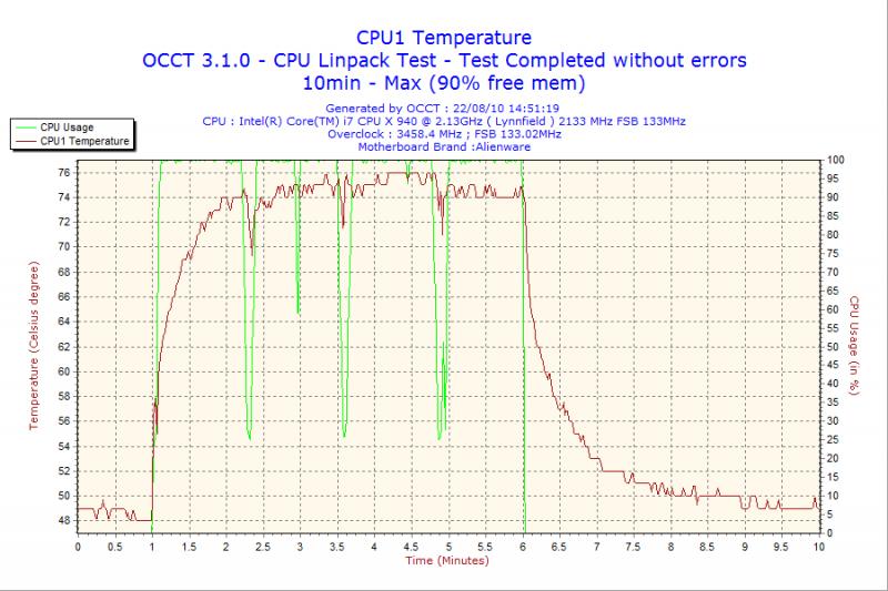
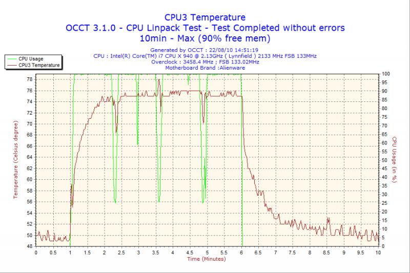
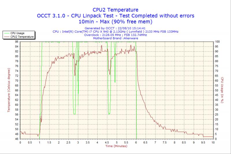
Stock clocks with P95 + furmark (8xaa, post processing, stability, xtreme burn, 1600x900):
I've included two images to show the clock cycling from stock to throttled 3d clocks:


This leads me to believe it is either an AC adapter power limitation similar to what is happening to the Dell SXPS 1645, bios issue or a mainboard design flaw. Either way, stock settings under full load should not have caused the system to throttle, especially since it was not under any thermal stress. I had someone with a Sager 8690 perform the same test and he reported no throttling.
Overall, I think this could potentially be bad news for everyone because the system will throttle itself when it's under maximum stress. I'll test this theory out further with Crysis Warhead and a few other games later on but if others would like to contribute, that would be great. This could also be a limitation of my own system so I'd encourage others to test and see if it happens to you.
Please include your configuration details as well as driver version. Lastly, if anyone has an M17x adapter with them and does get throttling, you could plug the M17x adapter into the M15x and see if it still happens. This would give a definitive confirmation of whether or not it's an AC adapter limitation. I have an M17x adapter on order but it will not get here until Monday or Tuesday of next week. Unfortunately, I cannot use a battery test since the system defaults to 3D clocks (383/301) despite the high performance profile being set to utilize 100% GPU power when unplugged. EDIT:I have confirmed that the M17x adapter DOES NOT solve the problem.
-----------------------------------
EDIT: Ran OCCT PSU test and this is what GPU-Z recorded:

The spikes are when the GPU cycled to full stock speeds and the rest was when it throttled.
EDIT 2: The notebook also throttles at underclocked settings! This does not bode well at all for the M15x.
EDIT 3: I'm attaching GPUz and Tmonitor log files that show what happens during the cyclical throttling.
---------------------------
UPDATE 12/08/09:
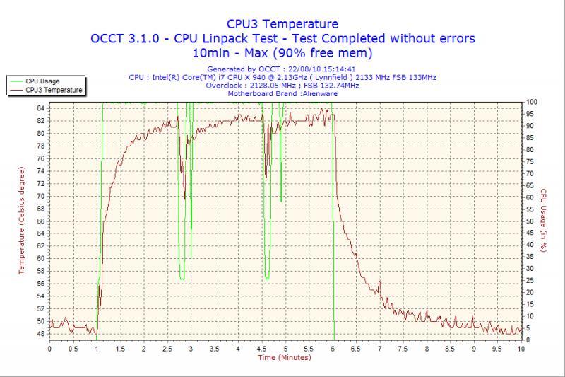
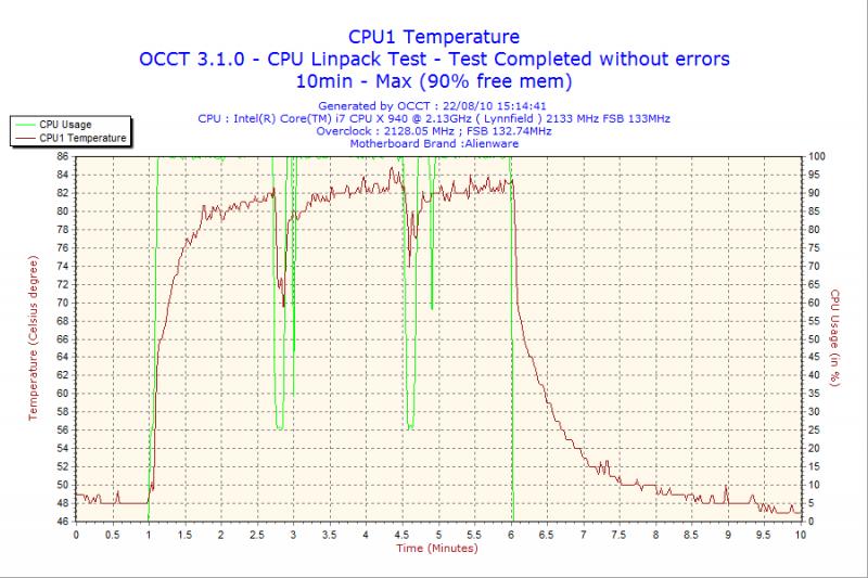
With turbo disabled in the bios, a bit more information is shed on the throttling issue. Notice that each time the 4 cores drop below 100% load, the GPU throttles with them. At peak CPU load (100%), the GPU stays at 100% until the CPU is throttled below 100% and with it the GPU also scales back it's clocks. Normally the GPU cycles far more frequently when Turbo mode is enabled but with it disabled, the rate of the GPU throttling is much slower.
Normally when Intel Burn Test is used by itself (not in conjunction with furmark), all 4 CPU cores stay pegged at 100% but when Furmark + Intel Burn Test are run together, the CPU clocks begin throttling together with the GPU clocks. This seems to further reinforce the idea that this throttling issue is power related.Click on the HD button to view the movie in 720p (in full screen) so you can see the clocks more clearly.
<param name="movie" value="http://www.youtube.com/watch?v=0cWy8rieIJI&hl=en_US&fs=1&ap=%2526fmt%3D22"></param><param name="allowFullScreen" value="true"></param><param name="allowscriptaccess" value="always"></param><embed src="http://www.youtube.com/watch?v=0cWy8rieIJI&hl=en_US&fs=1&ap=%2526fmt%3D22" type="application/x-shockwave-flash" allowscriptaccess="always" allowfullscreen="true" width="560" height="340"></embed></object>
---------------------------
UPDATE 12/19/09: Using a beta build of ThrottleStop by unclewebb, I was able to further test how and why throttling occurs and believe it is a power issue. Specifically, when the CPU multiplier was set to 10x on an i820 processor (1333 MHz), the GPU did not throttle at stock clocks of 550/950/1350 using the furmark + prime95 synthetic benchmark. However, if the GPU clock frequency was raised beyond stock settings, it would immediately throttle during testing even with the CPU frequency at 10x. Furthermore, other users have reported real world findings and have noted the CPU does not need to be at 100% on all 4 cores, rather even 2 cores at 100% + turbo mode is sufficient to cause GPU throttling. In one users case (Arkhias), the throttling was not cyclical but rather it caused the GPU to stay throttled when he was in a busy part of a game (Dalaran in World of Warcraft).
-----------------------------------
IMPORTANT UPDATE 12/21/09: Throttling Fix
***DISCLAIMER: I TAKE NO RESPONSIBILITY SHOULD ANY DAMAGE OCCUR TO YOUR SYSTEM. TRY THIS AT YOUR OWN RISK!*** The research behind solving this throttling issue is ongoing and as such, the instructions are subject to revision.
I think I've stumbled upon a temporary fix that will enable everyone with an M15x to run the system at max clocks under max CPU/GPU load. The throttling fix as of right now is a two part fix. One involves forcing the GPU to run at any clock you set via RivaTuner and the other is forcing the CPU to stay
at maximum load without throttling down it's active load state. Don't look to task manager to measure the CPU load, it is not reliable. If you want a true measurement of your CPU load state, use RealTemp 3.50. With that said, here are the steps to fix the throttling:
INSTRUCTIONS FOR THROTTLING FIX:The following are steps to resolving the throttling issue for both the CPU and GPU.-
To fix the GPU throttling, use RivaTuner:
1. Download RivaTuner 2.24c
2. Next, go to RivaTuner\Overclocking\Global, expand it and for "MaxClockLimit" set it to 300 and "DisableClockTest" to 1. Next under Rivatuner\NVIDIA\Overclocking set "EnablePerfLevelForcing" to 1.
3. Finally, go to the Main tab, under the driver settings, click the half arrow next to "customize", click on "system settings", go to the overclocking tab, enable driver level overclocking, set it to performance 3D and set your default GPU clocks. Towards the bottom, you will see, "force constant performance level", set that to performance 3D as well and click apply.
-
UPDATE 1/3/2010 for CPU Throttling Fix:
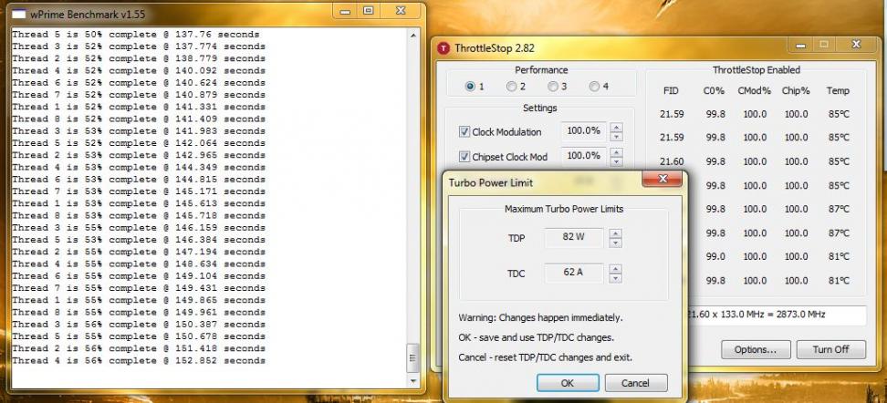
I've been working with UncleWebb in testing for an easy to use solution for the CPU throttling portion of the throttling fix. Well thanks to his mad programming skills, we now have the latest release of ThrottleStop which will solve the CPU throttling problem! The instructions are simple, download the program, turn it on, checkmark both the chipset and clock modulation boxes and set them to 100%. You must enable ThrottleStop each time you want to play a game that pushes the CPU to ensure maximum gaming performance and CPU utilization. My own testing has shown that with ThrottleStop, CPU performance gains are as high as 50%! If you find ThrottleStop useful for your day to day use, please consider donating via PayPal to UncleWebb for all his efforts. He did all this free for the community so a small donation is the least we can do. If you are interested in donating, please PM me for information.
If you have done everything properly, you will see the following result:
-
Video Bios Flash for Overclockers: WARNING, THIS COULD BRICK YOUR SYSTEM IF SOMETHING GOES WRONG, USE AT YOUR OWN RISK!
As promised, the instructions for flashing your video card are now available along with the necessary files. Please keep in mind that I have only tested these on my M15x and they work fine. Flashing your video bios can be risky and if done wrong will brick your video card. There are ways to recover it using a blind flash but that is left up to you to figure out. I only recommend this option for those that wish to overclock their video cards while using the rivatuner GPU throttle fix:
How to make bootable USB to flash the AW M15x Video Bios
1. Download the HP USB Key Utility: HP USB Disk Storage Format Tool - v2.1.8 Download - EXTREME Overclocking
2. Download the Windows 98 system files: Windows 98 System Files Download - EXTREME Overclocking
3. Download the bios .rom files (I've included the original oldbios.rom file and modified newbios.rom files) + nvflash files here: Download flashfiles.rar from Sendspace.com - send big files the easy way
4. Install the HP USB Key Utility
5. Launch the HP USB Key Utility and do the following:
- Insert your USB thumb drive.
- Select File system as "FAT32"
- Select Format Option as "Create a DOS bootable Disk..."
- Checkmark the box that says, "Quick Format"
- Locate the directory you extracted the Win98 files.
- Format the USB key using the the Win98 files.
6. Copy all the files from step #3 to the USB key
- nvflash.exe
- newbios.rom
- oldbios.rom
-etc.
7. Set your M15x bios to boot from USB Storage Device.
8. Attach the USB key to the system, reboot and it will load a dos prompt.
9. At the dos prompt you will need to type: nvflash -4 -5 -6 –A –y newbios.rom and when it asks if you want to flash the file, press ‘Y’.
10. You are done! If everything went well, you will now have 1v for your 2nd level 3D clocks which should enable you to overclock your GPU using RivaTuner. Be sure you do not use NST to overclock, only RivaTuner will do the job if you are applying the throttle fix.
-
1
-
Furmark: Native resolution (for me it's 1600x900), 16xAA, checkmark the stability test box, checkmark the xtreme burn button and also checkmark the post processing button.
-
I found this while reading the Guru3D forums: RadeonPro BETA: Automating 3D settings - Guru3D.com Forums
It's got a ton of nice features that almost everyone will find useful and it's very complimentary to the CCC. Pictures speak a thousand words so take a look:


For those with multigpu setups, the force vsync + triple buffering option is a gold mine since it will allow you to setup the game profile inside radeon pro and then it'll automatically detect whenever you launch a particular game and enable triple buffering. This remedies the wavy line issue without much increase in input lag or performance loss. Furthermore, you can force AA profiles in games that don't support AA.
-
2
-
-
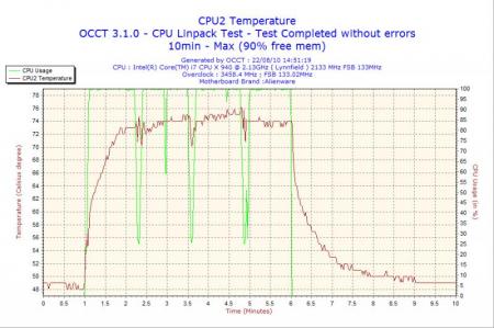
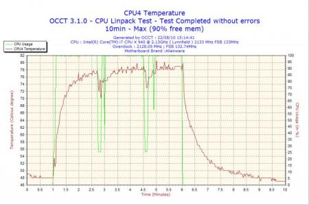
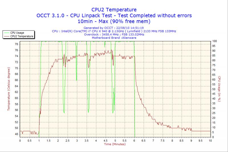
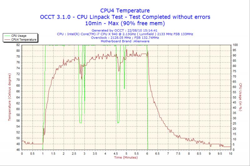
Ok I'm sure you're all aware of me whining about my CPU temps because even with the TDP set at 70W, if I ran Wprime 1.55 1024MB for over 3 mins, my CPU temps would skyrocket to the 95-97C range. Well I got fed up with it so I gave the CPU retention mod another try AND I bent the heatsink a bit using the sheer force of my superman hands.

BUT here's where the difference starts: For the CPU retention mod, you can't simply guess and apply 2-3 turns like the GPU mod and think you're set. It's a tricky game of varying the tension between the 4 screws so to gauge which ones needed tightening and which loosening, I put the metal cover back on, connected the xfire cable, kb and control cover and fired up the system with the TDP at 82W and let WPrime 1.55 1024MB fly. With throttlestop giving me real time temperature measurements, I alternated between tightening and loosening the 4 screws until I found the sweet spot. It's very delicate because if one of the screws is overtightened, the CPU temperature goes from say 84C to 97C in 2 seconds! Once I determined the optimal settings, I closed up the system and ran WPrime just now and here's my absolute max temps:

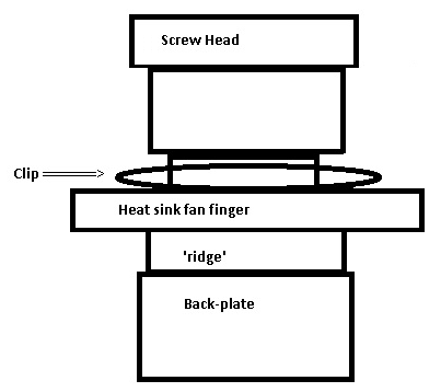
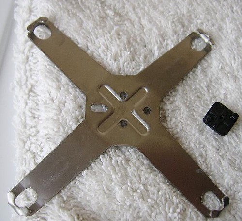
Note that this CPU retention mod requires removing the c-clips and positioning up top in the same manner the GPU mod works (diagram below).
I used the tool on the right to remove the c-clips on the CPU heatsink:

Pictorial of how the retention mod should look:
Temperature measurements with retention mod @ 62W:
Temperature measurements with retention mod @ 82W:
-
4
-
-
Well here we go, our first speculation thread and don't worry, it won't get shut down!
 Here's what we THINK will be the specs so far:
CPU: Sandy Bridge with HM67 chipset
Display: ???? Mostl likely 16:9 and possibly WLED. We're holding out hope for RGB LED/IPS.
Build materials: Looks like this baby's going to be aluminum like the R2. -->May possibly have a combination of soft touch + aluminum base.
Graphics: Dual 6970M and 460M SLi (yeah weak and could change).
PSU: 330W PSU now 240W.
-
1
-
-
Copying over my original article:
How to OC the M17x-R2 using SetFSB:
Background information
I'll start with how I figured it out:
1. I saw the Asus guys unlock their bclk using setfsb and figured the PM55 can't be too different from the HM55 and decided to give it a shot. The first step is to download SetFSB, switch the clock generator to ICS9LPRS365BGLF, click GET FSB and let it populate the addresses.
2. I realized Dell already gave us the keys to OC'ing the BCLK in the bios so I started by setting my system to default and doing a capture of the addresses setfsb spit out. I then incrementally increased the OC from 1-5% and observed the changes in the offsets (see attached photos). Here's the notes I made last night when testing all this:
Offsets stock vs 5%:
00h:21/29
0C: 0D/20
0F: D8/98
10:31/34
=====================
Offsets 1% vs 2% changes:
0F: 98/18
10: 32/33
=====================
Offsets 3% vs 4% changes:
0F: 98/18
10: 33/34
======================
Offsets 4% vs 5% changes:
0F:18/98
10: 34/34
=======================
Offset changes for 0F from stock to 5%:
Stock: D8
1%: 98
2% 18
3% 98
4% 18
5% 98
Offset changes for 10 from stock to 5%:
Stock: 31
1%: 32
2%: 33
3%: 33
4%: 34
5%: 34
Offset chagnes for 00 from stock to 5%:
Stock: 21
All the rest: 29
3. The key thing to realize is that once you enable overclocking in the bios, offset 00h switches from 21 to 29, 0C to 20 and both stay that way for the duration of BCLK manipulation. The other two offsets that always change are 0F and 10. What I found is that if you lower 0F from 98 to say 95 and leave 10 as is (default is 34 when OC'ing at 5%), it raises the BCLK. Likewise, you can put 0F at 98 and incrementally raise the BCLK by increasing the value of offset 10 from 31-39 (it locked on me at 40).
So in summary
1. Download and turn on SetFSB 2.2 (freeware version)
2. Switch to clock generator ICS9LPRS365BGLF
3. Change offset 00h to 29, click update and apply. Change offset 0C to 20 and click update/apply.
4. The other two offsets (0F/10) are the ones that let you manipulate the BCLK as high as your system will allow and so 0F can be changed to 98-95/18 and offset 10 can range from values 31-39.This method of BCLK overclocking has been shown to work with non-extreme CPU's that range from the 520M all the way up to 840QM.
Please note: If SetFSB does NOT show anything in the registers for your machine, it's because you need to do the following:
Step 1) change windows font resolution from medium or large to normal(in the control panel under font sizes) .
Step 2) adjust registers because SetFSB can't reproduce large font sizes!!!
Images to reference offset changes from 1% to 5% (red=changed offset, green=offset unchanged):
Changes in offsets at 1%

Changes in offsets at 2%

Changes in offsets at 3%

Changes in offsets at 4%

Changes in offsets at 5%

-
1
-
-
This cooling mod was originally performed by Ashterfere and is being reproduced here:
This post will be updated with the latest info as we get it.To start, we need to identify a few parts so you know what to look for.
GPU Die
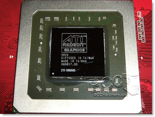
This is the GPU core. Be careful, its fragile. The HD5870m wont have a metal bumper around the edge, this is just an example image.
Retention Clip
Also known as a retention arm, retention bracket, etc.
This holds down the GPU cooler to the GPU die and ram.
C-Clips, AKA 3/4 washer
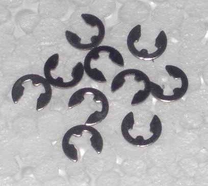
These are attached to the screws on the retention clip. They keep the screws held ONTO the retention clip so they dont fall off.
So, to begin.
The "Problem"
I use the term "problem" lightly, as the heat of the HD5870m is within specification. The problem I think is that the default GPU cooler is not being used to anywhere near its full potential.
We will be using Furmark to measure worst case scenario temperatures. No game will ever reach these temperatures, they will in fact run the cards much cooler. But this gives us a good benchmark to work off.
Here is the average temperatures of a user (TurbodTalon) in the forum running furmark before the mod:

71.5c on the display i/o temp, 92.5c on the memory i/o and 82.5c on the shader cores.
These are actually very good temps. My temps before this were ~80c, ~105c, ~90c respectively, as it is winter here and I run the heating pretty high.
If you do ALL of the mods listed here, you will get something like:
61c on the display i/0, 69.0c on the memory i/o and ~65cc (the above screenshot has min accidently ticked instead of max) on the shader core. Keep in mind, my ambient temps are around 27c in the above screenshot (higher than TurbodTalon's) - your result will probably be lower again.
This is a temperature drop of 10c, 24c, and ~22c respectively.
This is huge - and all we are doing is rearranging some things and doing some ghetto.
First you need to know straight up - depending on your country this may or may not void the warranty of your graphics cards. Even if it does, the dell technician that comes out to service you if you need it may not even care OR notice you have done this mod.
Now, how to do it?
First, this is what you need.
- AS5 or similar THIN thermal paste
- TX-3 or MX3 or similar THICK thermal paste
- Electrical tape or similar heat resistant tape that doesnt leave residue
- Time
- Courage
We will begin from easiest mod to hardest.
DUCTING MOD
All of the heatsink ducts dont sit flush or sealed against the fan ducts. This means air goes out the sides, and doesnt go 100% through the fins. Inefficient, lots of noise and no cooling.
I used duct tape to fix this. Same with CPU cooler (optional). I recommend electrical tape to avoid any residue that may hamper your warranty.
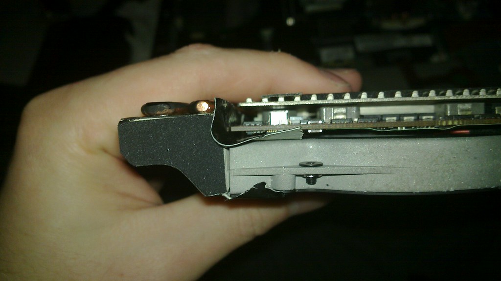
Its fiddly getting it all in for the cards - what I did (optional!) is removed ONE screw from each graphic's cards blower fan assembly.
The screws to remove are the ones you CANT see when the card is in place slotted into the MXM slot.
Obviously, you cant screw this screw, so you need to remove it.
The other 2 should be accessible when you place the card into the mxm slot.
This essentially makes the fan/heatsink/gpu one part, and easier to manage.
What this mod achieves is slightly quieter fan noise and more air through the copper fin arrays.
THERMAL PAD MOD
Here is a rough diagram of how the dell GPU heatsink sits on the Graphics cards:
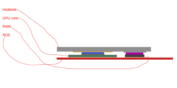
The pink area in the above diagram is the rather thick and nasty thermal pads that dell use on their cooling block.
The blue area is the OEM dell thermal interface material that dell use.
As you can see, the height of the thermal pads on top of the memory actually increases the gap between the GPU die and the GPU core.
What we want is:
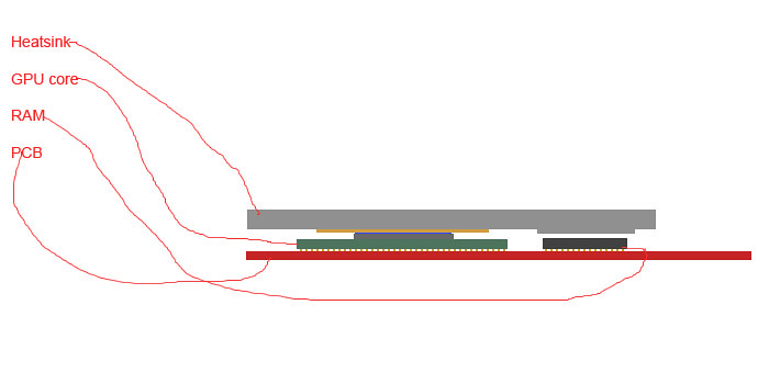
Here we have removed the thermal pad, and replaced the bad thermal interface material with something thinner (AS5 in my case).
This provides much better contact with the GPU core, and reduces the gap between GPU and RAM to < 0.5mm.
So, heres the step by step.
STEP 1:
Remove the heatsink and clean off all the thermal interface material.
Save the thermal pads somewhere safe, in case you ever need to RMA
Put them in a ziplock bag so no dust gets on them.
STEP 2:
Remove the thermal interface material from the GPU die and RAM chips of the card.
STEP 3:
Place a half grain of rice size drop of your THIN thermal interface material on your gpu die.
STEP 4:
Place a full grain of rice size drop of your THICK thermal interface material on each ram chip.
STEP 5:
Replace the heatsink and screw it down, then replace the cards.
RETENTION CLIP MOD
This one is not for the faint of heart. If you are not careful you could crush your GPU die, and then its GG to your GPU.
This mod is done to increase the pressure of the heatsink, so it contacts the GPU Die better, and contacts the ram better.
This mod should be done at the same time as the thermal pad mod, and requires the thermal pad mod to work.
STEP1:
Remove the c-clips from the screws on the retention clip. An easy way to do this is to stick a small hobby probe or screwdriver into one of the 2 gaps on the inner ring of the c-clip, then push the c-clip away from each screw. It will pop out easily, but make sure you direct it towards something that will catch it.
I lost one that decided it wanted to be an astronaut.
I hope it has a safe voyage.
STEP2:
Remove the screws from the retention bracket.
STEP3:
Re-attach the c-clips to the screws while they are OUT of the retention clip.
STEP 4:
Re-attach the heatsink to the pre-thermal pasted GPU board.
STEP 5:
VERY CAREFULLY put the screws with c-clips attached back into the retention clip, and then screw each screw in numbered order just enough to grip without coming back out. This should be 2-3 turns at most. No more, or you may crack the GPU die.
STEP 6:
Check to make sure the board isnt warping to much on one corner. If it is, you have screwed that screw too tight. The board may bend a little, but it will be barely noticable. What will bend the most is the GPU Heatsink. We want this, as it closes the gap between the ram and heatsink even more.
And you are done.
With all of these mods, not only will you get better temps, but the GPU fans will never spin higher than 30%
Cooler AND quieter, with just a bit of fiddling.
-
2


Radeon Pro for ATi powered notebooks
in AMD
Posted
Sure does and it has a built in update feature for the program + skins.