


Khenglish
-
Posts
1799 -
Joined
-
Last visited
-
Days Won
67
Content Type
Profiles
Forums
Downloads
Posts posted by Khenglish
-
-
Without overvolting it should not turn off. Where did you connect the ID line to GND? The PSU needs to see the grounded ID line, not the laptop.
-
Dell systems have led error codes. When the system fails to start, check and record the sequence that the capslock, scroll lock, and num lock are blinking in. You can then look up what this sequence means failed.
-
2 hours ago, Alibi said:
Hi, I tried to solder the original plug-in jack of my 180w PSU to a DELL ( Flextronics) 240w PSU. I connected the ID wire to the ground and white to white as you instructred, but the Adapter shuts down 1-2 min after GPU is under full load. I have a Clevo P157SM and upgraded 2 summers ago to a GTX 980M which needed more power. It is only doing this while using prema's vbios. I didn't change any settings. My laptop was working well with the 180w as well, but many users reported that it needs more power. Need a bit of help. Thanks!
What are you doing that shuts it down? If you're cranking up the GPU voltage you can still shut down a 240W with a single 980m.
-
No it cannot. Gsync requires the nvidia card to directly output to the display. Sm series laptops send display output through the integrated graphics to the display and cannot be changed.
The card will still work fine though, just without gsync.
-
 1
1
-
-
1 hour ago, p150em_user said:
Can you please provide more details on the necessary hardware modifications? Looking at your post and the service manual it is still not clear to me what exactly needs to be done, from what I can tell I need to connect DP wires to lines which exist but are not connected to anything.
Edit: there is also a confusing "dGPU DISPLAY PORT" page in the service manual, which seems not be be connected to the dGPU at all
I can provide more details, but it will take a while to create something someone can follow.
A lot of the service manual is copy/paste from the previous highly similar P150HM, which was dGPU output only but otherwise extremely similar to the P150EM. Because of this some schematics are mislabeled.
-
1 hour ago, p150em_user said:
Hi, I have a p150em and want to drive a 4k monitor at 60Hz by connecting it directly to dGPU (7970m) via the eDP connector (only DP pins needed). Is this possible without any hardmare mods?
No, the 2nd post details the required hardware modifications.
-
2 hours ago, Av.pavan4u said:
Thanks a lot for prompt reply.
What I understand is, I can stitch together through Hex editor and do the required mod to it(such as http://donovan6000.blogspot.in/2013/06/insyde-bios-modding-advanced-and-power-tabs.html) and once done I can break them at the same offset to write it each bios individually to their respective chip.
Can you provide some link/short write-up to gain Read/Write access(BIOS_CTL or similar thing) on BIOS, so that I will be able to write through ME system tools w/o needing open the board each time I do want to put back the modded one.
Pavan.
Yes, you just merge and later separate at the same offset.
After you pull the chips and mod the firmware you can disable the write protect lock using FITC. After this there is no need to pull the firmware chips.
There is some other lock that I vaguely remember, but there's some trick to get around it via software means.
-
You just stitch the files together in a hex editor. When flashing separate them at the same point. Usually the bigger chip's image is first, so tag the smaller image on to the end of it.
-
57 minutes ago, pcmaniac said:
In the last end i found and ordered a MSI GTX680M Vbios 80.04.33.00.24.
I read on the forum that this will fit directly inside my p170hm machine and work.
Only thing i need is modded drivers.
I really want to know. Do you guys know if the clevo p150hm machine heatsink will fit in a p170hm?
And same with the battery? Is it the same?
Thank you.
Yes the heatsinks will fit. The gpu heatsinks are identical. The p170hm cpu heatsink is better than the p150hm heatsink though.
The battery will not fit.
-
1 hour ago, Prema said:
Who needs a new Notebook if an almost 5 year old system can beat them all: https://goo.gl/4Jn76E
So you ran 2076 core? I'm surprised it's still around 1k lower than a modded 980m.
-
2
-
-
@J95 What system uses that small MSI 1080? With heatsink mods that'd fit in standard MXM systems.
-
1
-
-
With the 680m the voltage slider does not work in Nvidia inspector. You need to flash an overvolted vBIOS.
ASIC quality has no impact on overclocking other than power consumption. Low ASIC quality = higher power consumption.
-
Yes, a 230W will be fine with no overclocking as well as mild overclocking.
-
Some prema mod require a .inf mod for the 970m and 980m, and some don't. He has special non-public mods for many systems that circumvent the .inf mod requirement.
As for compatibility with the P150SM, you don't need any modded bios at all. It will work with just a .inf mod. With a 180W PSU you actually do NOT want to run a prema vbios, as prema disabled the power limit. With that off your 180w psu will shut down in games if you get a 980m, even if you don't overclock. If you run the stock 980m vbios your 180w psu should just barely be ok.
You can flash the p150sm prema mod system bios if you'd like, but it is not essential.
-
1
-
-
Artifacts is always a faulty bga. It can likely be saved by baking it. Let me know if you are interested and I'll tell you how to bake.
-
Optimus is always enabled, but some programs will block optimus from shutting down the 980m. For example programs like GPU-z might, or say Blizzard's Battlenet program. Try closing programs and see if the 980m shuts off.
Also changing the power setting in the Nvidia control panel to "optimal power" may help as well.
Bios and modded drivers are not the problem.
-
Any 580m will work well with no bios flashing. It can be Clevo or Dell (Alienware).
-
1
-
-
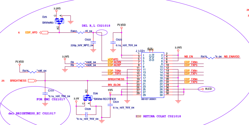
Yes P370SM, P370EM, and P170HM all have the same eDP connector. The non-functional P150EM and P170EM connector is the same as well.
What would work is if you could find a 30 pin to 40 pin LVDS cable. LVDS on HM, EM, and SM systems is surprisingly very similar to eDP on SS and later systems. Only 2 wires would need to be switched. Also let me know if you find such a cable because I want a 40 pin cable, but don't want to spend hours making one.
-
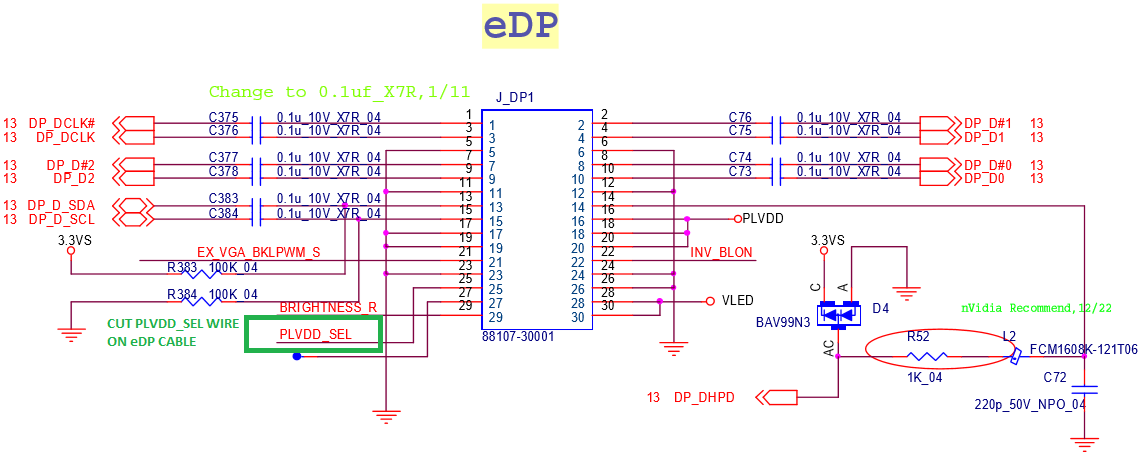
Also seeing people use a 5V to 3.3V step-down converter when the motherboard had a fully functional 3.3V and 3.3V select circuit made me post to NBR for the first time in 4 years. I do not understand how no one noticed that when using the motherboard schematic on the exact same page to build an eDP cable. The circuit is literally directly to the right of the first image above and I cropped it out.
-
I have attached an image of the line to cut and leave cut for 3.3V instead of 5V.
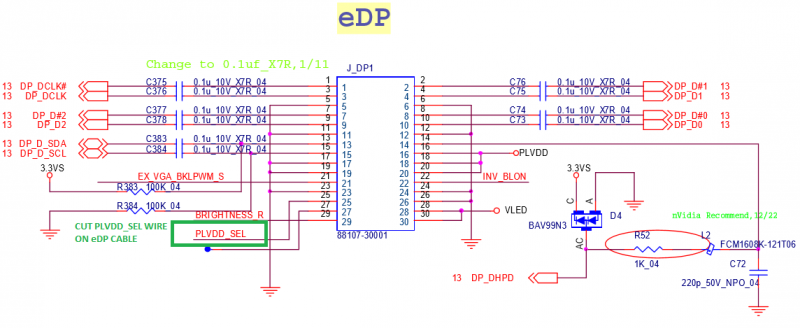
For reference, below is the W230SS/ST eDP connector. You need to rewire the eDP cable to match your connector above.

-
1 hour ago, bennyg said:
I've been following DARCODER's thread on NBR. I looked up the schematics and the eDP looks the same as the P37xSM output. I'm trying to order the cable that was used in that thread - a QHD for W230SS/ST - Australian shop is being a bit slow and it will take AT LEAST 2 weeks once confirmed since they have to order in from o/s.
My P370EM has the eDP (I have not seen a mobo shot without it? maybe very early rev only lacked it) but is not a 3D model.
The only mod that is needed is stepping down pin 25 PLVDD from 5V to 3.3V and I have a cheap buck converter on its way from China, it says it can handle "75W" so should be ok with the ~15W the screen will draw through it, and the amount of heat dissipated because of inefficiency
But we will see. DARCODER runs his on 5V but it looks like the panel's ghosting, who knows if it was damaged during modding/testing or that is due to the overspec 5V on that pin it's getting now
If it doesn't work at least the panel will go in my P870DM. Which I know will work... because it is the exact laptop in that thread
")
DO NOT USE THE W230SS/ST CABLE UNMODIFIED. THE WIRING IS DIFFERENT BETWEEN THE W230SS/ST AND P370SM MOTHERBOARD CONNECTORS AND YOU WILL HAVE A FIRE.
You need to cut the cable in half and resolder the connections to be correct for the P370SM motherboard eDP connector wiring.
The P370SM3 only uses the 30 + 20 pin eDP cable just like the HM3 and EM3. Making an eDP cable for any other screen is still necessary.
No need to step 5V down to 3.3V. There is a voltage selection circuit. If using the 3D eDP cable you cut the line that pulls the select signal low and that's it. You have it easier than me as I had a FET pulled as well that I had to add.
-
So I figured out how to mod memory clocks (checksum location is different from standard 980m vBIOS). This let me drop P0 mem clocks to 6.2ghz, and from there I can overclock to whatever it can handle. 6350 appears to be fully stable max mem clock. So now I can use P0 for regular use, just with poor memory clocks.
The default voltage is 1.168V with this odd vBIOS. Since this is a 1.3V max voltage vBIOS & 980m load line regulation is all wrong, 1.168V drops to 1.13V under load at the voltage regulation, with at core voltage some unknown amount slightly lower. When topping out clocks for the voltage (~1320MHz) I've had the card hit 220W under full load... and my cooling capacity tops out at around 200W. This is a bigger problem than the memory clocks. Hopefully @Prema can save me.
I noticed on the 980m that over 2/3 of the voltage feedback reading circuit is missing, and this may be why the 980m voltage regulation is so terrible (At the VRM the 1.3V vBIOS is about 40mV too low, while 1.2V vBIOS is around 40mV too high). I have a dead 980m with still functional core voltage that I will test my ideas on (not gonna risk sending 3.3V to my working 980...). Unfortunately I do not have the 980m PCB schematic, but I do have the VRM schematic, so I have to guess a little at what's wrong.
-
You will need to do a .inf mod to run the 260m. A guide is below:
-
I put a Dell 485m into a P150EM and it worked, so I would expect a 470m to work as well. What brand is the 470m? Is it Clevo, Dell, MSI, or HP?
M6600 bricked, fan loud once, now only warm spot on chassis.
in Dell Latitude, Vostro, and Precision
Posted
You're saying the laptop warms up with AC plugged in even when off?