imsolidstate
-
Posts
63 -
Joined
-
Last visited
-
Days Won
8
Content Type
Profiles
Forums
Downloads
Everything posted by imsolidstate
-
StamatisX, what is the maximum current you've managed to pull with your setup? Is it 15A? And what was the voltage at the maximum current? Just wondering what your total power consumption was. Also, you shouldn't need a diode bridge since you aren't rectifying any negative voltage. You only need one diode per power supply input, to make sure that a power supply never sinks any current.
-
The motherboard doesnt regulate most of the power for the video cards. It comes almost straight off the line from the DC jack. It only regulates the 3.3 and 5 volt rails, where power consumption should be fairly similar for most cards. The card itself regulates the main power input to the core, which is the approximate 19.5 volts from the power supply.
-
@Nospheratu yes you can do that. From the series resistor it's a straight run through to the motherboard. If you wanted to put the ID chip inside the laptop, there are a few locations right by the power jack. There is an inductor that is the first thing the ID signal goes to, that would probably be the best place to do the modification. You need to pull the inductor so that the ID wire no longer goes out to the power supply. Because of the skip ROM command, there can't be any other devices on the bus. Then just solder the data pin of the chip to the EC side of where the inductor was and use two jumper wires to ground the other two pins. That should keep it nice and low out of the way of the CPU heat pipe.
-
It works. You have to make a couple modifications, it doesn't work with the DS2502's third pin floating like it is on the PCB, and you have to convert it to passive power so the motherboard bus master can pull the line low. Here is a guide with pictures and stuff. 330 Watt power supply for Alienware M17x » imsolidstate
-
I tried the modified 330W PS in my machine. The BIOS reports it's a 240W adapter. It works, but there's still a problem I have to work out. The 330W power supply has an actively powered connection to the 1-wire memory, where the old supply was passively powered. There is a bit of a quirk with how the power supply is powering the memory device, because it is not readable immediately upon powerup. I think this might have something to do with how the power supply is handling the pull-up. When I plug in the supply and turn on the computer, it reports an error for the power supply, even though it says 240 in the BIOS. However if I reboot instead of shutting down, the power stays on but when it reboots I don't get any errors about the supply. Intermittently though OSD reports an unsupported adapter when loading Windows. I had the same issue when I was scanning the supply with my test equipment. It wouldn't always respond. I think the 330W PS might be pulling the line too high for the M17x motherboard to communicate reliably. I measured it last night at something like 8 volts unloaded. I think I will try converting the memory to passively powered, I think that should do it. Hopefully.
-
Well, I cracked open both of my power supplies and located the 1-wire EPROMs. The 330W is a DS2501, so there wasn't any room to reprogram anyway since that is a 512kb device. The 240W is an unmarked SOT-23 package on mine, but it returns the family code 0x09 so it should be a DS2502. I noticed that the PCB for the 330W had both SOT-23 and TO-92 package footprints available, so I transplanted the memory chip from the 240W to the 330W. The second ground pin is floating on the 330W PCB, I soldered it to the other ground pin on the package just in case. My desk is a mess of circuit boards and test equipment and the power supply is completely open so I haven't plugged it into the laptop yet, but I successfully interrogated the 330W power supply and got the 240W data back. It should work now with the laptop thinking it's a 240W power supply. I'll try it tomorrow. So I wonder what went wrong with the OP's chip transplant?
-
I got a 330W power supply and dumped the 1-wire memory. It has the same structure as the 240 and 90 watt Dell models. It's also got the same family code as the 90 watt supply, 0x11. I haven't found out what that is yet, but it is compatible with the DS2502 that I have been working with. I built a 1-wire programmer by modifying my mbed code for the write memory and status register commands, which was kind of a pain because of the requirement of the 480us 12V programming pulse. I'm going to write up a schematic and the code on my website so I can remember what I did. Unfortunately, the status register bits for page protection are different in the 330W. Where the 240 write protected the first two pages of data, the 330 write protected the second two unused pages of data. That means I can't write the new data to a different page and use the page redirection bytes to update the memory contents. Since the memory is add-only, I can't change 330 into 240 either. That means the 1-wire memory will have to be replaced with a new one that isn't write protected, so it can be programmed with the information from the 240W. A DS2502 is only about $2.50 at Mouser so I will probably get some. I'm disappointed though because if the 330W supply had the same page protection as the 240W I could have programmed it and had it working without even cracking the case. I guess Dell must have figured out that was a weakness and fixed it.
-
The dell one I posted here on my thread about the 6970m and the R1 motherboard. The Clevo vBIOS is the one I downloaded from here. Regarding the Dell vBIOS: I figured out that if you have a USB memory device in one of the slots it will shut down, but it takes a few more seconds than normal. It will also go to sleep, but after a few seconds it wakes up on its own and says Windows did not restart properly. It still hangs if the screen goes off.
-
I tried tweaking the vBIOS and boosting the memory voltage, but no luck. Guess I'm stuck with it this way. Thanks for the suggestions everybody.
-
It's hard to say if the card is defective or not, since the graphics part works properly on the Dell vBIOS. If you uninstall the video drivers while running the Dell vBIOS the computer shuts down fine. There is something wrong with the way the Dell vBIOS code and the Catalyst driver communicate that makes it hang. I've tried looking in the system logs for an error but haven't found anything. My guess is the card is defective because one of the memory locations is corrupt. I'm guessing the Dell vBIOS doesn't use that corrupted location or maybe that location just contains LSBs, while the Clevo vBIOS uses that location for MSBs and thus produces the corrupt data. The last thing I was thinking about trying was boosting the memory voltage a little, or maybe reducing the memory clocks with RBE.
-
Well part of the problem is I can't get the OEM driver to load. It's a Dell card, but when I try installing either the M18x or M17xR4 drivers the install fails with an error about wrong version of Windows. I had to try to manually install the driver to figure that out since the Catalyst installer just skips installing the video driver without saying anything. Yeah, that's how I've been doing it. I was pushing the voltages last night to see how low I could get them and I bricked the card anyway. I have to pull it and in-system program it. Your right the GPU could have a problem; that's kind of what I suspect, this is the card with the out-of-tolerance voltage regulator. @Michael - It's an R1 with an R2 motherboard and 840QM. The wierd thing is the Dell vBIOS seems to only have an issue with turning the screen on and off, and going to battery. It seems like ACPI or something. I wonder if you could somehow disable the card's ACPI functions to get it to shutdown properly. I can't wait until I can get 7970ms.
-
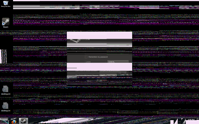
I can't figure out how to get my 6970 working properly with Windows 7 64. It works fine with the mobile Catalyst drivers on the Dell vBIOS, but won't shutdown, sleep, go to battery etc without crashing. When I flash to the Clevo vBIOS, I get serious screen issues when the Windows desktop loads, but it will shutdown and sleep properly. I attached a screenshot of the desktop. I've tried quite a few versions of the Catalyst driver with no change. When I try to install the Clevo or Dell driver, the Catalyst installer just skips installing the driver for the video, and if I manually try to force it to install from the inf it says it can't install because of wrong version of Windows. I have tried setting the clocks and voltages in the vBIOS so that they are the same value to make sure there isn't an issue there. The only other difference I notice is that when I pull up the Dell vBIOS in the RBE it says it can't find information about overdrive. I'm not sure what to do to fix it. I either need to modify the Dell vBIOS where success is unlikely, or figure out why the AMD driver doesn't like the Clevo vBIOS. Anyone know what is going on here? Thanks in advance.

-
Thanks svl7. I'm not sure the MXM signal would work, since I think the EC directly controls the brightness of the display alone. I don't think the PWM for brightness is muxed with the MXM connector. It would be a better fix though if it was possible.
-
I wrote some code for my mbed and dumped the contents of the 1-wire EEPROM in my 240W power supply. Here is the output: Read ROM: 0x09 0x1A 0xF8 0xB2 0x08 0x00 0x00 0x73 Read memory pages: 0x0000: 0x44 0x45 0x4C 0x4C 0x30 0x30 0x41 0x43 0x0008: 0x32 0x34 0x30 0x31 0x39 0x35 0x31 0x32 0x0010: 0x33 0x43 0x4E 0x30 0x4A 0x39 0x33 0x38 0x0018: 0x48 0x37 0x33 0x32 0x34 0x35 0x39 0x36 0x0020: 0x43 0x32 0x32 0x35 0x34 0x41 0x30 0x30 0x0028: 0x32 0x28 0xFF 0xFF 0xFF 0xFF 0xFF 0xFF 0x0030: 0xFF 0xFF 0xFF 0xFF 0xFF 0xFF 0xFF 0xFF 0x0038: 0xFF 0xFF 0xFF 0xFF 0xFF 0xFF 0xFF 0xFF 0x0040: 0xFF 0xFF 0xFF 0xFF 0xFF 0xFF 0xFF 0xFF 0x0048: 0xFF 0xFF 0xFF 0xFF 0xFF 0xFF 0xFF 0xFF 0x0050: 0xFF 0xFF 0xFF 0xFF 0xFF 0xFF 0xFF 0xFF 0x0058: 0xFF 0xFF 0xFF 0xFF 0xFF 0xFF 0xFF 0xFF 0x0060: 0xFF 0xFF 0xFF 0xFF 0xFF 0xFF 0xFF 0xFF 0x0068: 0xFF 0xFF 0xFF 0xFF 0xFF 0xFF 0xFF 0xFF 0x0070: 0xFF 0xFF 0xFF 0xFF 0xFF 0xFF 0xFF 0xFF 0x0078: 0xFF 0xFF 0xFF 0xFF 0xFF 0xFF 0xFF 0xFF Read status registers: 0xFC 0xFF 0xFF 0xFF 0xFF 0xFF 0xFF 0x00 The string from memory page 1/2 in ascii form: DELL00AC240195123CN0J938H7324596C2254A002 It's a DS2502 (Family code 0x09, the first byte of ROM). The datasheet indicates that the first two pages are write protected (0xFC). If the 330W PS is the same way, it won't be easily reprogrammable. However there is something about memory page redirection that I could possibly use to change the value returned for a given read address. I will have to order a 330W PS to see if it is the same chip. I dumped the contents of a 90W dell PS, and got a different family code so I will need to figure out the part number of the 330W to see if it is reprogammable or would have to be replaced with one that's not write protected.
-
Well technically ascii characters are only 8-bit which is a char, an int is 16 bits. The BIOS probably just pulls in the three char values from the EEPROM to check and then display in the BIOS screen. I doubt it gets converted, but like you said there is no way to know. I've been staring at the EC code and comparing it to the datasheet hoping to find some connections, like this one and the PWM channels as well. So far I can't make sense of the EC code from the ROM. It doesn't match what is supposed to be there according to the datasheet. If ITE wasn't so tight lipped about their code maybe it could be disassembled.
-
I figured out what was wrong with my display being stuck on low brightness and how to fix it. It's CCFL backlit, not LED. The LED controller is probably different. If you have this problem and want to fix it yourself, see here: M17x inverter brightness fix » imsolidstate
-
I'm interested in this because I want to try two 7970ms. I can't afford it right now, but I've been messing with the adapter problem. As we know, the power supply integrates a 1-wire EEPROM and the EC interrogates it to see if its valid or not. I sniffed the 1-wire bus with my logic analyzer when I powered up the board, here is the results: 0xCC - Skip ROM 0xF0 - Read memory command (if it's a 2501) 0x08 - First memory address byte 0x00 - Second memory address byte 0xFB - Should be a CRC of the previous three bytes 0x32 - (2) 0x34 - (4) 0x30 - (0) Skip ROM means that it won't look for a specific ROM because there is only one device on the bus. Then it asks to read starting at 0x0080. The slave then outputs the checksum of the address and command to the master for verification. Then it starts reading out data as the master requests it. In this case it gets "240" and is done. 240 doesn't appear anywhere in the BIOS code, but it does appear in the BIOS settings screen. I don't know how the BIOS checks if its valid or not. I have yet to get a 330W PS and see what the requested string is. An easy hack would be to reprogram the EEPROM in the 330W so that it returns 240 from the appropriate memory location. This is what I plan to test when I get a 330W supply. I'll have to build a 1-wire programmer since they are a little different. Oh and the resistor doesn't really have a special value, it's just a pull-up to VCC since the bus is open-drain, and the devices can only pull it to ground.
-
6970m and original M17x (a.k.a. R1)
imsolidstate replied to imsolidstate's topic in Alienware M17x / AW 17
Okay I'm finishing this project up; I have to admit failure at getting the R1 and 6970 working together. Having the R2 mobo working means I don't really want to tear my computer apart for weeks on end again. I wrote two articles on my website, one for the 6970 and another with some more details on the conversion to the R2 motherboard. That post also includes files for download to dump / program the two flash memory chips on the R2 motherboard. Thanks to everyone for the help. -
6970m and original M17x (a.k.a. R1)
imsolidstate replied to imsolidstate's topic in Alienware M17x / AW 17
@mw86: Thanks. Unfortunately I was not successful at getting the 6970m running on the R1. It would have helped if the card was working when I was doing the majority of my testing and experimentation. It sucks that the card was dead so I was effectively wasting my time.... I am really hoping eBay's buyer protection will cover this, but I'm not holding my breath. After I hacked the card and got it working, all I did was test it in the R1 MB with a system BIOS that I modified the MXM info on. It wasn't enough to get the card to POST, there is still something else in the BIOS that is holding it up. Since I successfully got an R2 motherboard in my machine, I don't really have the motivation to tear it apart again and keep messing with the R1 board. Actually what I want to do is get 7970ms for it, maybe get the 300W power supply working in it too. The 6970 works with the vBIOS that it shipped with, which is not the Clevo vBIOS, however it locks up anytime the screen goes off. If I install the Clevo vBIOS it shuts down properly but I get bad screen tearing. Something else that I can't figure out at the moment is ever since I replaced my original R1 board the LCD brightness has been stuck on low. I've tried two different R1 boards and now the R2 board and they all do the same thing. Windows can't control it either. It's so dim I can hardly see the screen. I'm about ready to hack the inverter so I can have brightness again. -
6970m and original M17x (a.k.a. R1)
imsolidstate replied to imsolidstate's topic in Alienware M17x / AW 17
More good news. I went back to my hunch that lack of a power_good signal from the 6970m was holding up POST. Turns out I was right. I checked the two main regulators for what I think is the memory and for the core. The memory regulator was spot on, but its POK signal was being pulled low. So I checked the core regulator. Unfortunately it is so tiny and on the back side of the card that I can't test it with power on. I also can't see what the voltage is supposed to be because the VIDx lines that set the voltage are only valid with power on. However I did measure the core voltage at 1.04V, which is not unreasonable. So I decided to take a risk and cut the ISL62883C's PGOOD trace, since I knew vcore wasn't going to damage the core at 1.04V. Sure enough, it powered up and booted. I could only run it for a few seconds since the heatsink is removed. So, the core voltage regulator appears to have drifted enough that the regulator is saying it's out of limits. I'm not sure I can do much about it really, since the card is a mess of tiny traces and vias. I think what I might do is get it running and measure vcore against the commanded vore in software, see how far off it is and probably just run it. Maybe undervolt it a bit to be on the safe side. So my R1 board is supposed to come today, I can FINALLY test the 6970m in it with my modified BIOS, which was the whole point four pages ago. Sheesh. -
6970m and original M17x (a.k.a. R1)
imsolidstate replied to imsolidstate's topic in Alienware M17x / AW 17
SUCCESS! Finally something is working. I found this: Alienware Apparently it wont POST without RAM. That's a first for me. The R2 board is now running in my R1. I have an R2 motherboard, 840QM CPU, and R2 heat exchanger since the CPU/SB are in physically different locations on the R2 board. Now I'm wondering if the video worked without my MXM system info BIOS mod. I hate to pull the chips again just to reflash and find out. Anyone know if the R1 LCD works natively on an R2 board? Testing will continue! I'm not sure if the audio board will work or not, there are different part numbers for R1/R2 audio boards. More later. -
6970m and original M17x (a.k.a. R1)
imsolidstate replied to imsolidstate's topic in Alienware M17x / AW 17
Okay, I got my R2 motherboard and an 840QM. I have the same problem with the R1 board and the 6970m, fans spin constantly and nothing happens. I did some more research and figured out that it is probably hanging the system by not asserting power_good. Power_good is when all rails are within spec, before anything happens and before signals are applied to the bus. If the system is following the MXM spec then it shouldn't do anything until power_good is asserted. I figured out the other stuff I was looking at (SMBus) is probably just thermal info. The system reads EDID and other info from the LVDS DDC/Aux connection. Haven't sniffed that for the panel's EDID yet. So probably this card is dead. Nice $300 paperweight, since I have no information on the card I can't even try to fix it. I think I might check out the eBay buyer protection on this one. Anyway, putting the 260m in the R2 motherboard and trying to boot gives me a flashing num/caps. I've searched Google but have no idea what this means. I thought it might have something to do with the LCD, since it's the only non-R2 part (everything else is disconnected). I verified this by checking the MXM system information in the BIOS. The R2 is requesting a 24-bit LVDS bus where the R1 LCD is an 18-bit bus. I modified the MXM info to fix this, updated the checksum, and flashed it. I had to pull the chip since it wont even POST. No fix though. Still flashing num/caps. Side note: the EC and BIOS code is split in the R2. The old flash location is now a 2Mb part that apparently just holds boot code for the EC. The first 2Mb of the ROM is mapped to the EC flash. Then there is a 32Mb flash in between the CPU/SB that holds the rest of the code. It's mostly offset from the 2Mb of the EC code, but there is some stuff in the first 2Mb. So with the R2 you can't simply flash the ROM image to the chip, it's split and there's some unknown code in the first 256k. My R1 MB is supposed to be here tomorrow, hopefully this one actually works because the shipping from these guys is RETARDED slow. However I really think the 6970m is junk so I don't know if I'll put it in or keep plugging away at getting the R2 board working. I would much rather have the i7 over the C2Q, if nothing else than for the hyperthreading. I'd appreciate if anyone could tell me what flashing caps/num is supposed to mean, and if there is a place to potentially repair my 6970 (besides Dell of course, can't imagine what they charge). -
6970m and original M17x (a.k.a. R1)
imsolidstate replied to imsolidstate's topic in Alienware M17x / AW 17
I bought an R2 MB, should get it by the end of the week. Maybe there's still hope. -
6970m and original M17x (a.k.a. R1)
imsolidstate replied to imsolidstate's topic in Alienware M17x / AW 17
Can anyone comment on putting an R2 motherboard in an R1? I just had a look at the R2 motherboard, and it looks pretty much identical except the MCP79 has its own heat exchanger, it's not part of the CPU heat exchanger. All of the other connectors appear to be in the exact same spot as the R1. Maybe I'll have the eBay folks exchange me an R2 MB instead. -
6970m and original M17x (a.k.a. R1)
imsolidstate replied to imsolidstate's topic in Alienware M17x / AW 17
Okay. I got my "pulled from new computer 100% tested" motherboard from eBay. The LVDS connector had been repaired. Brightness is stuck on low. Checked for the brightness PWM signal from the EC to the panel, nothing. So whatever took out the LVDS on this board also took out the EC's PWM. So the EC is bad and I will have to send it back. However, it still works so I did some testing while I had it. I flashed my MXM-modified SBIOS, but no change. According to the MXM software spec (which has disappeared from the internet at the moment) the MXM card should respond on SMBus before any other signals such as power_good become valid. So I hooked up my logic analyzer to the MXM SMBus line. My LA doesn't have a good sample depth because it has a high sample rate, so I couldn't get a good picture of no MXM module vs. a working MXM module. I needed to get the whole sequence to compare, but my LA only has a 256k buffer so I can only sample for a second or two. The bus runs at about 67kHz so I need 500kHz sample rate for the I2C decoding to work properly. An interesting thing I found was that the board is built to prevent the MXM module from receiving SMBus communication. It's buffered through a switching transistor to only allow the MXM module to write to the bus. I tried shorting the drain/source of the transistor so the module could receive replies but it evidently doesn't because nothing changed. What I did figure out with my 6970m is that the SMbus lines are in some sort of tri-state condition. They don't switch with power on and stay around 1.7V. This is an invalid bus condition. Since SMBus is the first thing that is supposed to happen, things don't look good. I don't think I will pursue this any farther as I have no way to verify that the 6970m is actually working. I also don't have a logic analyzer at the moment with sufficient sample depth to get a clear picture of the SMBus activity on startup. AMD ignored my request to join their development group so I don't have any data for the card. I will probably put it back together when I get a working MB and sell it for a newer release.