

tmash
-
Posts
45 -
Joined
-
Last visited
-
Days Won
1
Content Type
Profiles
Forums
Downloads
Posts posted by tmash
-
-
Hi all,
After I saw this result: http://hwbot.org/submission/2830783_0.0_cpu_frequency_core_i7_4700mq_4550_mhz , I got interested to replicate it with a similar method and decided to share my steps to score higher than a desktop 4.4ghz 4770k (according to cinebench ;))
Intel Stock microcode has a Turbo multiplier bin glitch that allows unlimited multiplier increase, I used prema's bios and removed a cpu microcode update to let the cpu run the stock glitched microcode. I will share the bios file, use it at your own responsibility and if you know what you are doing.
1) Download or dump your BIOS, if your bios is ami (my case) then use AFUWINx64
2) Get AMI Aptio UEFI MMTool v5.0.0.7 and UEFITool, HxD (or your fav hex editor)
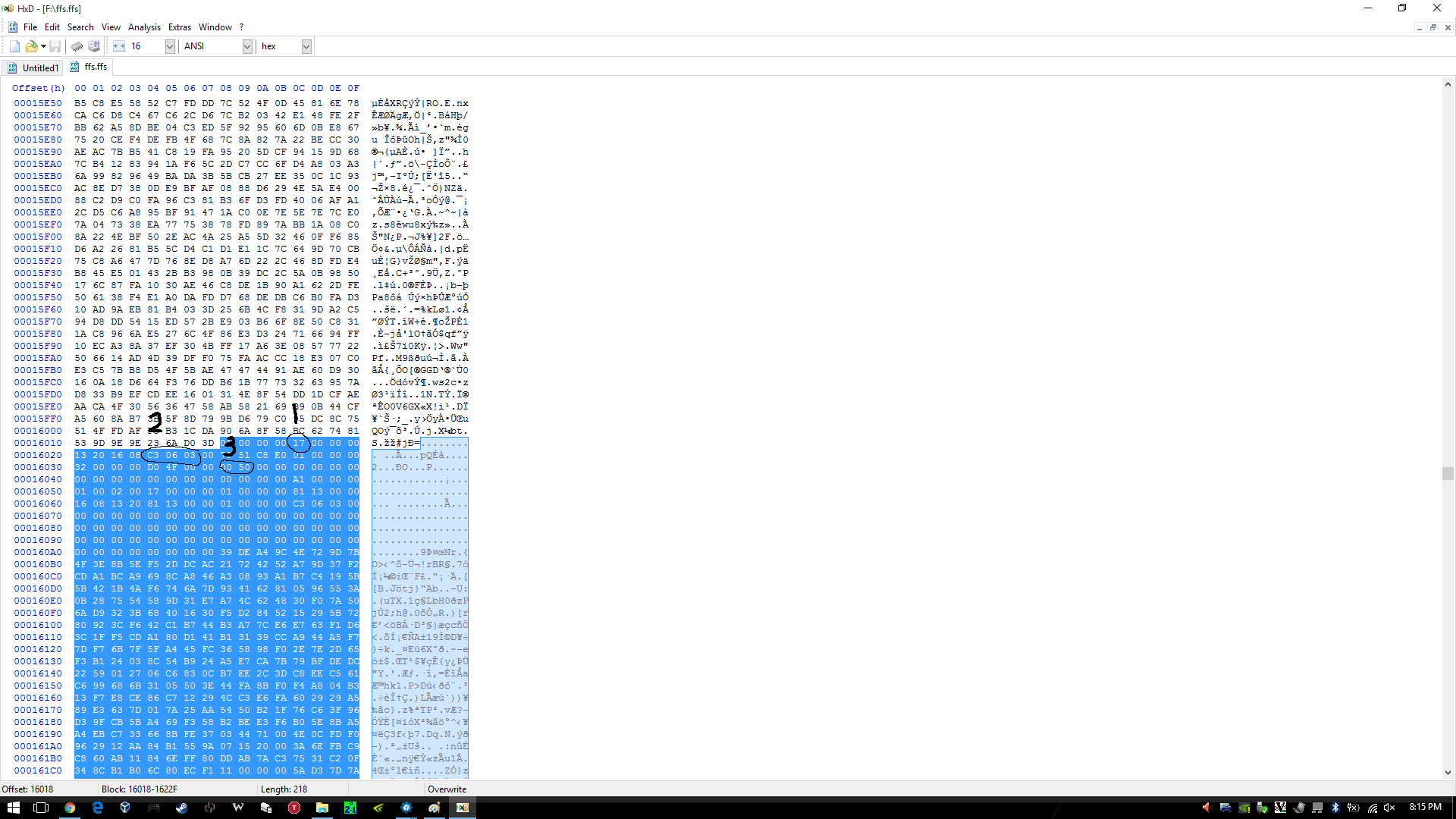
3) Open your BIOS image with UEFITool, then File>Search, in our case Haswell has the following ID:
QuoteC3 06 03
, enter C3 06 03 in Hex pattern dialog click OK
4) You can see the last four Hex pattern result, double click the first result and a structure item in the main dialog will be highlighted, right click>Extract as-is to a folder (be sure to be neat and organized or you will mess things up)

5) Do the same with the third result and save it as a diff name other than the first one
6) Now in the folder you have saved the 2 files from step 4&5, open the first one with HxD(any hex editor) and look for
QuoteC3 06 03

be sure to choose Datatype:Hex-values then hit search
7) Press F3 to find again till you reach this pattern(highlighted):
8) (1) Indicates the microcode version, 17 in this case, we want 00 (cpu stock), (2) the platform ID (the search context we reached at) (3) the microcode length = 5000 (in my case) in reverse (important to know when the microcode ends in order to remove).
9) Adjust the cursor on the beginning of the highlight text/microcode (01) right click>Select Block>Length>5000 or whatever in your case
10) Delete the highlighted blocks (after step 9) then save the file
11) Do the same with the second result from step 3 to 10 then save
12) go back to UEFITool, double click the first result like you did in step 4, right click the highlighted structure in the main dialogue > Replace as-is then choose the FIRST file you edited in HxD
13) Double click the third result and follow step 12 with the SECOND file you edited in HxD
14) You will see "Rebuild" in action row, File>Save image as> P15SM04.PM2 in my case (can be any name as long as your flashing tool recognize it)
15) Open AMI Aptio MMTool > Load Image > your modified rom > CPU Patch Tab and verify there is no 06C3 in CPU ID
16) Be brave and flash your BIOS
")
Windows Mod to remove auto update microcode on boot:
- Click on Start
- Type CMD in the Search box
- Right-click on CMD and choose Run as Administrator
- In the Command Prompt window and change to the directory where the file is located. To do this, use the CD command. You can follow the example below.
- to change to the Windows\System32 directory you would enter the following command and Press Enter
cd \windows\system32Now use the DEL command to delete the offending file. Type DEL mcupdate_GenuineIntel (and backup) Done!
Overclocking:
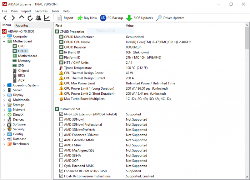
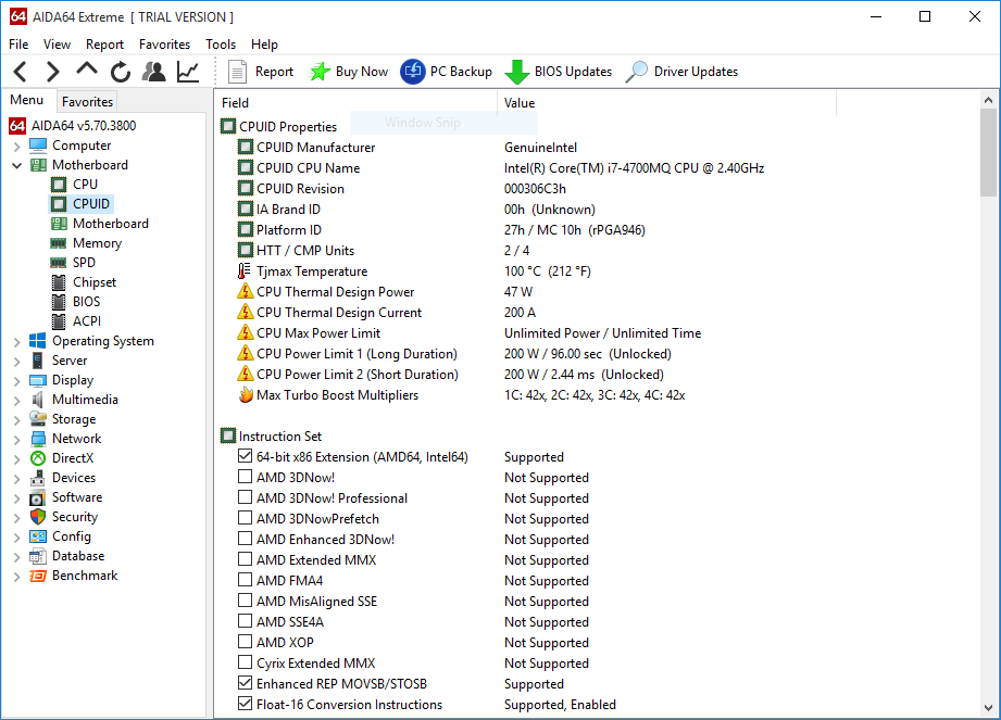
1) Check CPU MCID:Download AIDA64 , open AIDA64>Motherboard>CPUID and look at IA Brand ID, it should be 00h
2) Download the latest beta Throttlestop (not stable) in my case 810b2
3) Make sure you don't have XTU installed or running (especially at startup) or it will reset any changes in Throttlestop
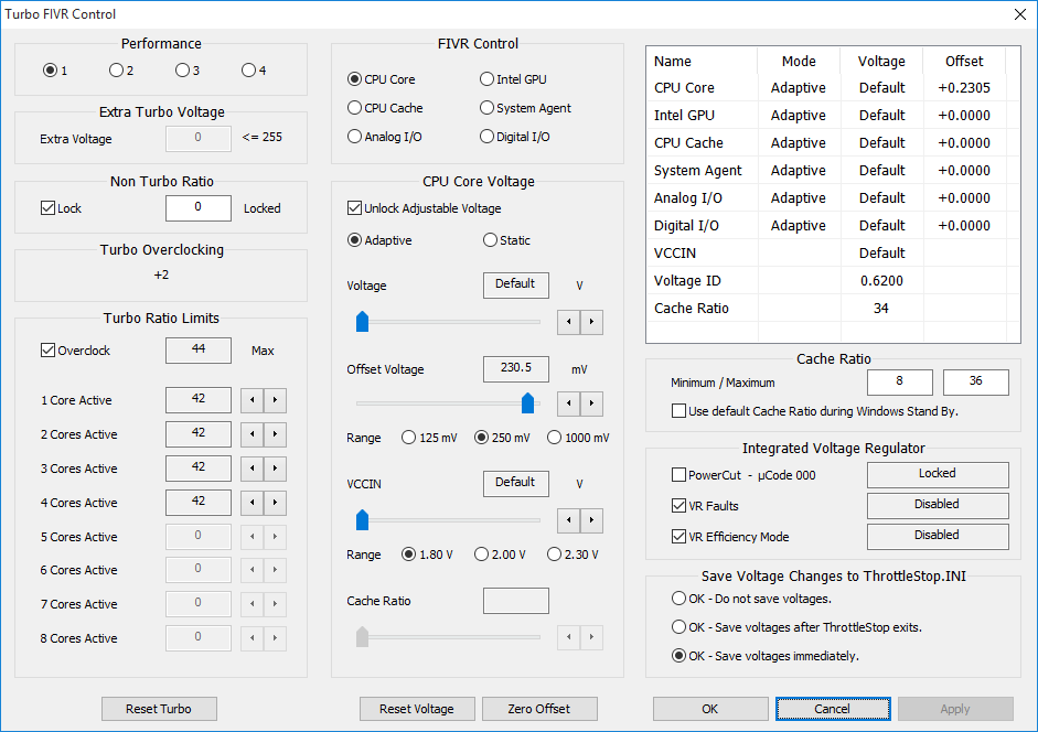
4) Open throttlestop, click FIVR and look at "[checkbox] Overclock [DIALOG] Max" and note it down
5) Now here is the magic! close FIVR and open it again, [DIALOG] Max value should increase by 2 (up to 80x max ~ 8ghz) everytime you open and close FIVR aslong as long as you increase one of the cores, LOL
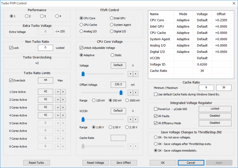
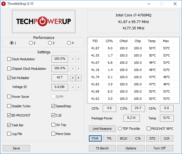
6) Increase "Set multiplier" to maximum after your final changes in FVIR (Iv set mine to 42x all cores, so I increased set multiplier to 42 aswell - note voltage ID is messed up ignore it)
7) Increase voltage in FVIR for stability by using cinebench run 3 times instead of prime95, as it stresses FPU which increases heat and tdp instead...
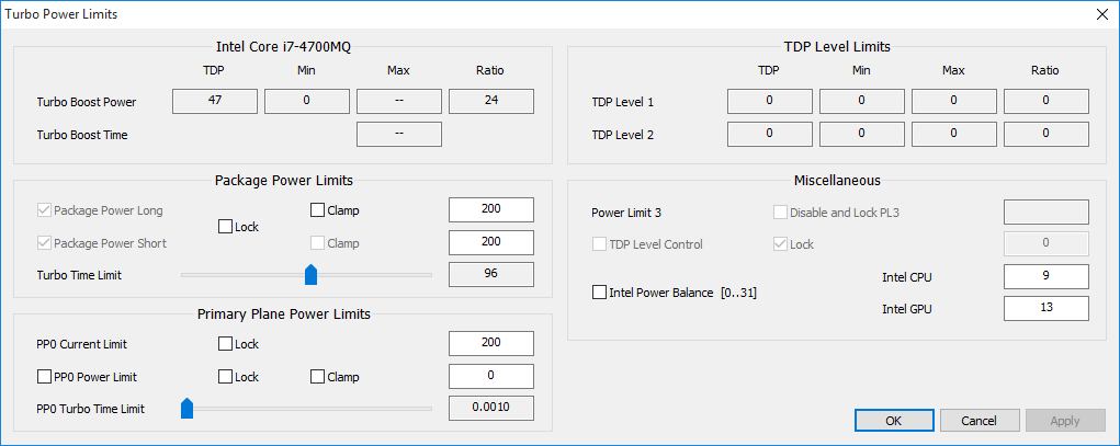
8) Unlock maximum TDP and turbo wattage in TPL, in my case:

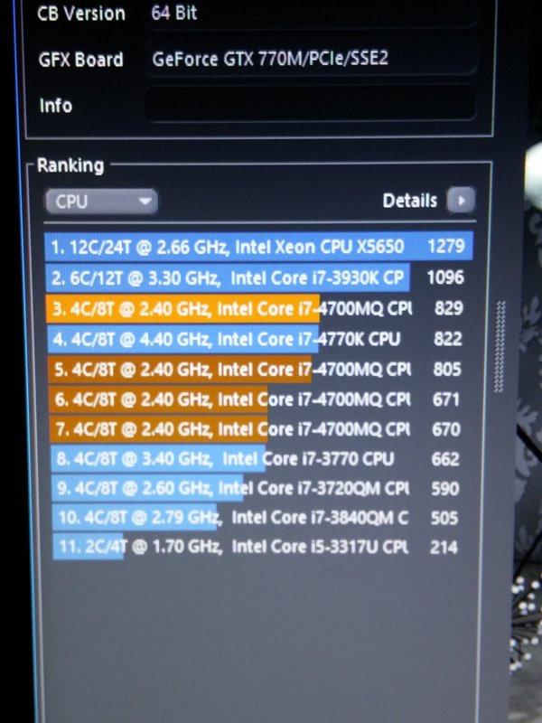
9) Done! Changes should be persistent as long as you dont save and exit from BIOS, here is my result in Cinebench with temp throttling (from 4.3 to 3.9 ghz), room temp 25-27 XD: (no.1 at 4.2ghz, no.7 stock latest microcode)
UPDATE: OCed RAM from 1600 to 1866, [email protected], +200mV adaptive vcore:
I'm also getting 852 with 4.5ghz with this adaptive voltage-like method:
Note: You can maintain maximum turbo multiplier bin with latest microcode after setting it in throttlestop (imp: no crash when testing; make sure its stable) then flash the latest microcode for bug fixes (more stable on my side at x45 with only +230mv, depends on your CPU, i7-4800+ will require less voltage), and you will still be able to set the bin high (up to 80x) as long as you don't crash...
Post your results and I'll copy it here.
Tips:
- I highly recommend lapping heatsink and use liquid metal thermal paste or any decent tp ( I used collaboratory liquid ultra) before doing this
-
-If your cpu throttles no matter what, try decreasing dynamic voltage in FVIR and look at maximum value the package power indicate while stressing, decrease the value by 10% in order to avoid rapid throttling (happens with bad TP)

- -Do not attempt the OC if you are looking after long service life wear&tear (I expect 2 years from now if I stress the cpu everyday for an hour, which i never do :P)
Happy overclocking, and don't melt your laptop
")
Thanks to Intel if they leaked this on purpose, kinda futureproofed my machine XD
P150SM 1.03.05 modded bios (at your own risk):
MOD EDIT: link removed, please use a clean BIOS base because of legal implications with Intel :
-
 6
6
-
Hello earth,
WARNING: although this is a semi-guide, what you're about to read isn't for the faint hearted XD, I'm not responsible for any damage, fire, death to your pet etcetera if you attempt to do it...
As you may already know, you cannot force custom timings on intel igps, unlike dGPU system only, since Intel IGP cannot do EDID overrides. More about EDID: https://en.wikipedia.org/wiki/Extended_Display_Identification_Data
The solution was to dump the EDID which can be done using modeline in windows registry, linux modeline, or dumping directly from the EEPROM (electrically erasable read only memory found physically in most screen logic) which should be straightforward as we need to actually reflash it with our modification simply over i2c interface using arduino (simple 328 with serial-to-usb, can be from 8$ to 25$ max) you can also buy an EEPROM programmer which can be slightly expensive.
The screen I have is a CMN1B, Chi .
Should also work with AOU 95% gamut screen, any screen with i2c interface to eeprom, you can actually trace it along the 18th and 19th pin from the LVDS cable, however it should be pretty visible.
So I ended up (easily), disassembling the screen as per this guide: [GUIDE] How to replace an LCD panel on a Clevo shell (pictures included) | NotebookReview
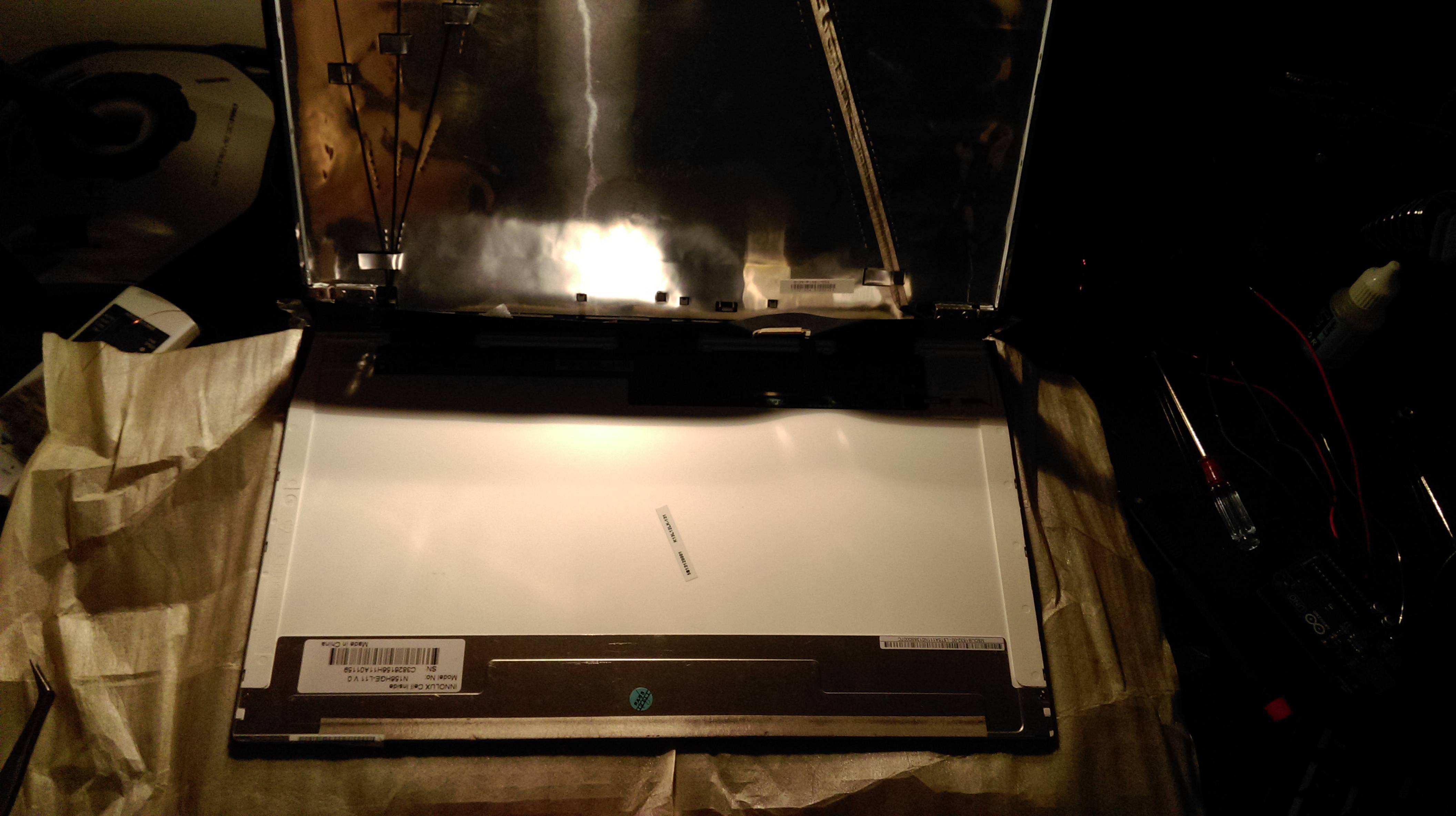 I've then cut the film from both sides then taped for making it easier to work (i.e: instead of cutting EEPROM's pin location):
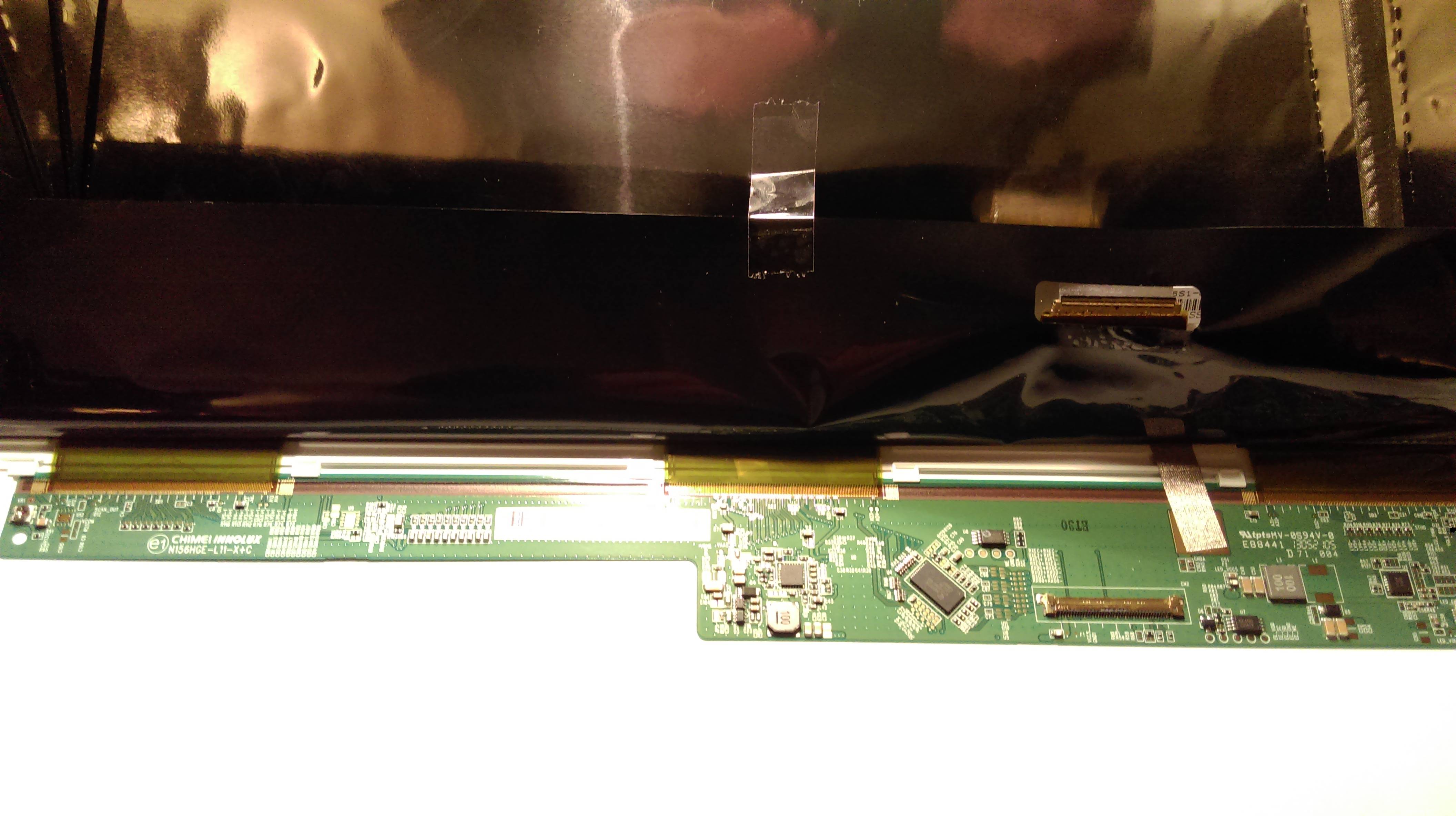
There are 2 EEPROMS in my case, identified it simply by looking at the test point tagging, EE_SC SD etc, should be similar in any other displays:
Tip size reference, basically any 15 to 30 watts soldering iron should work, unless the testpoints are tiny on other displays like AUO, though it is least likely you will ever have to desolder the EEPROM chip:
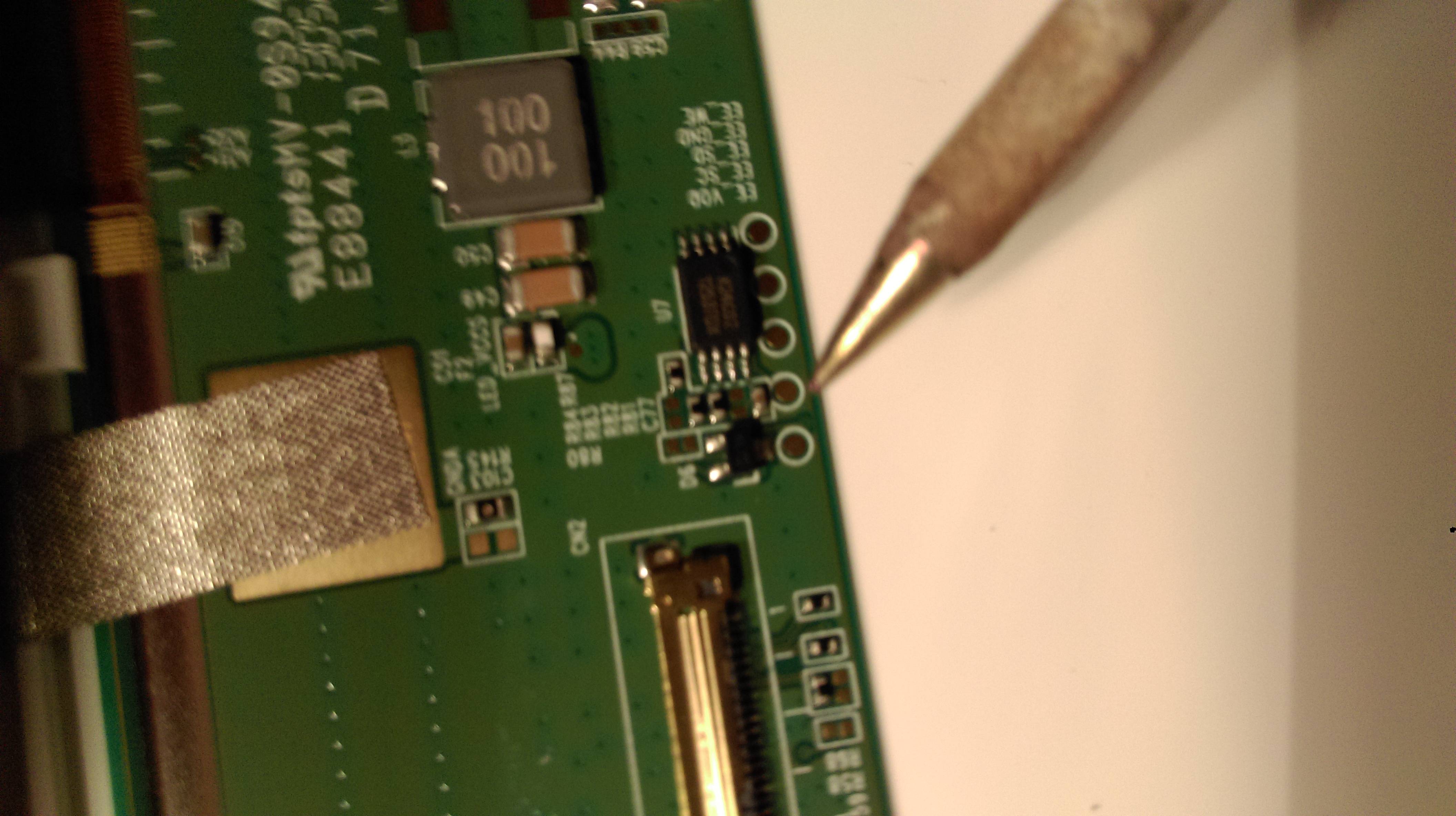
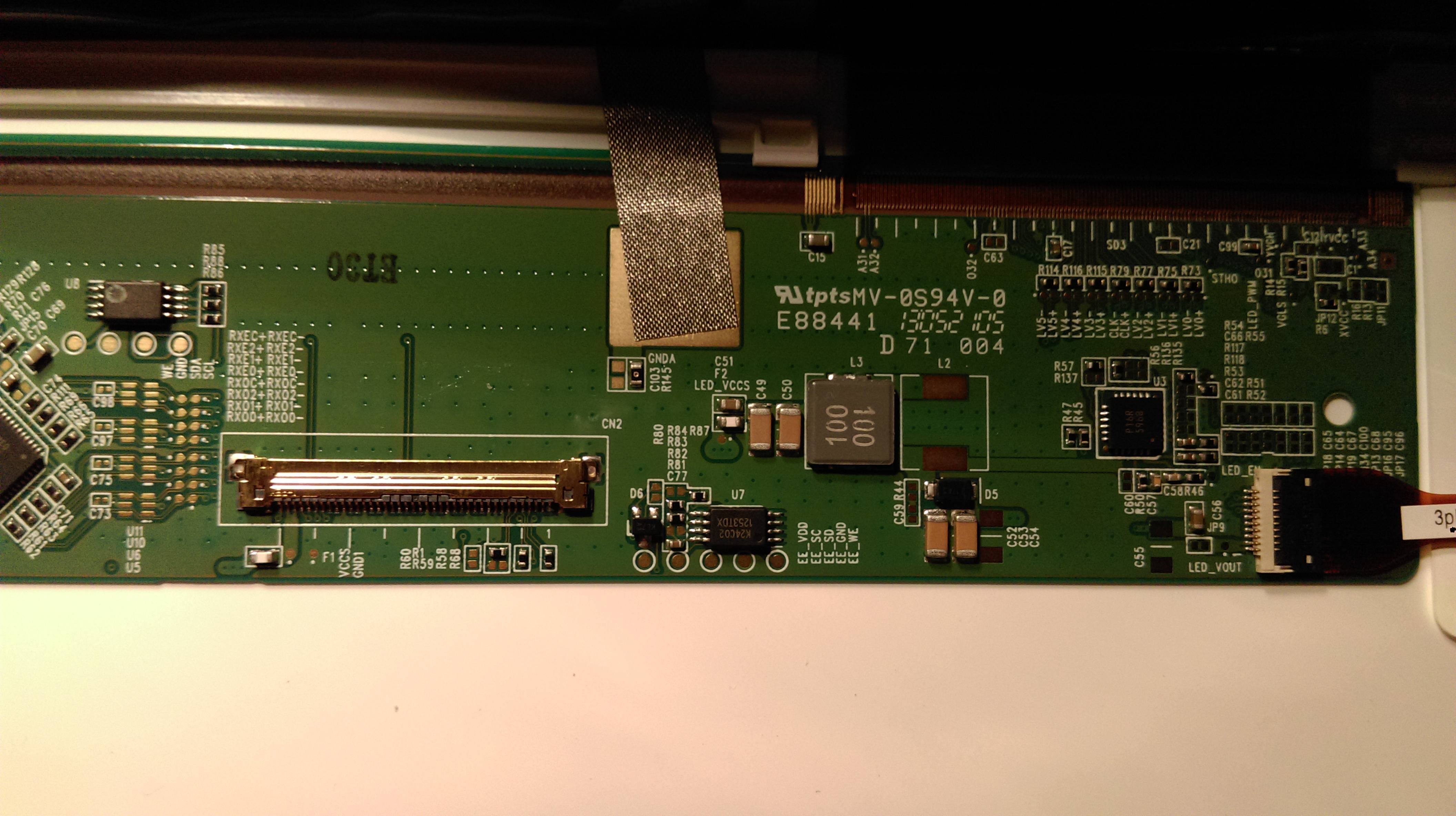
Sold'er! Roger that(You can see the EE_* tags, SC for clock, and D for data etc):
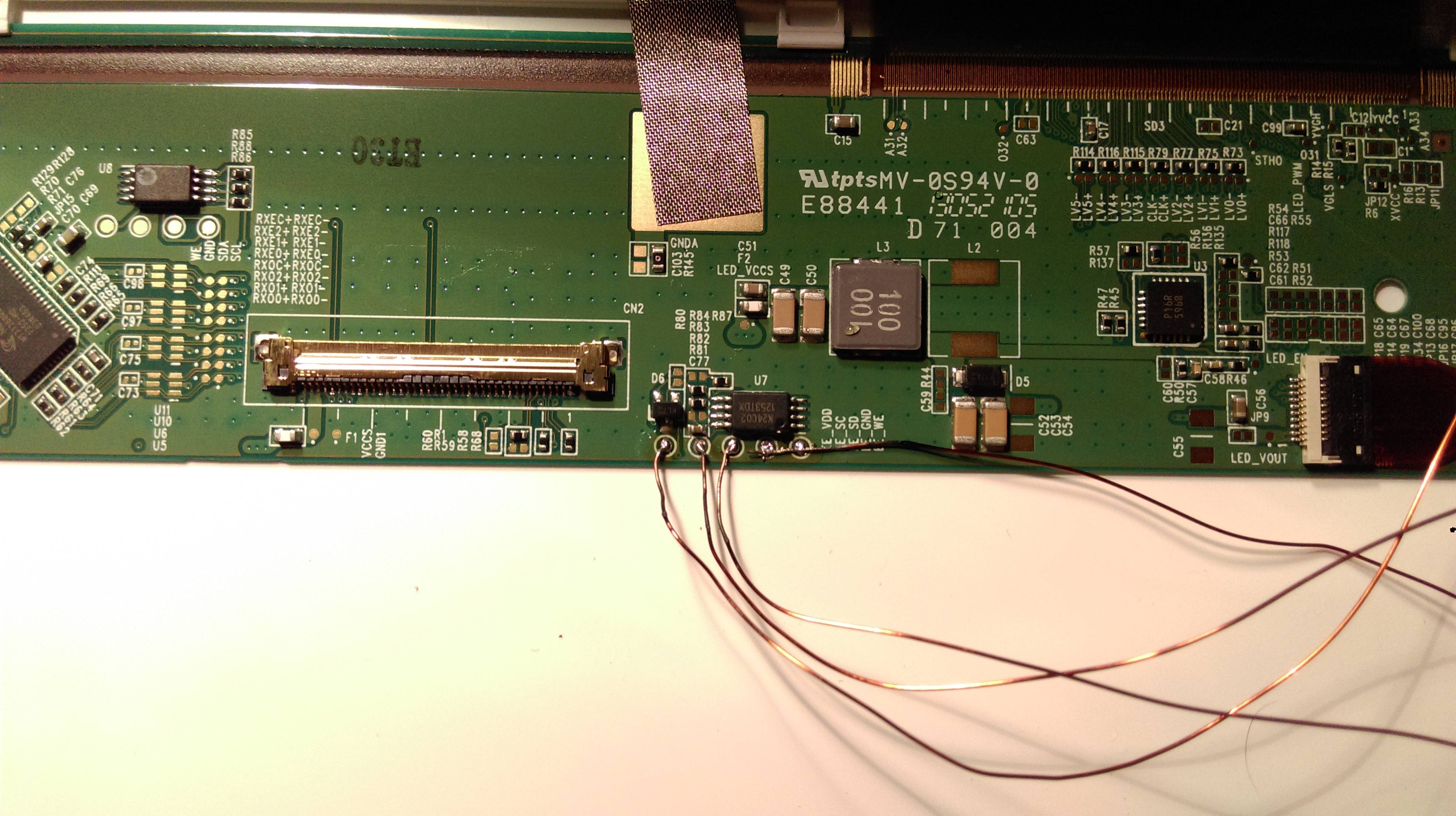
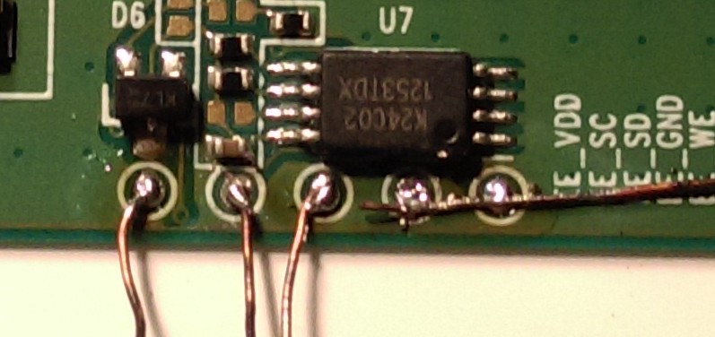
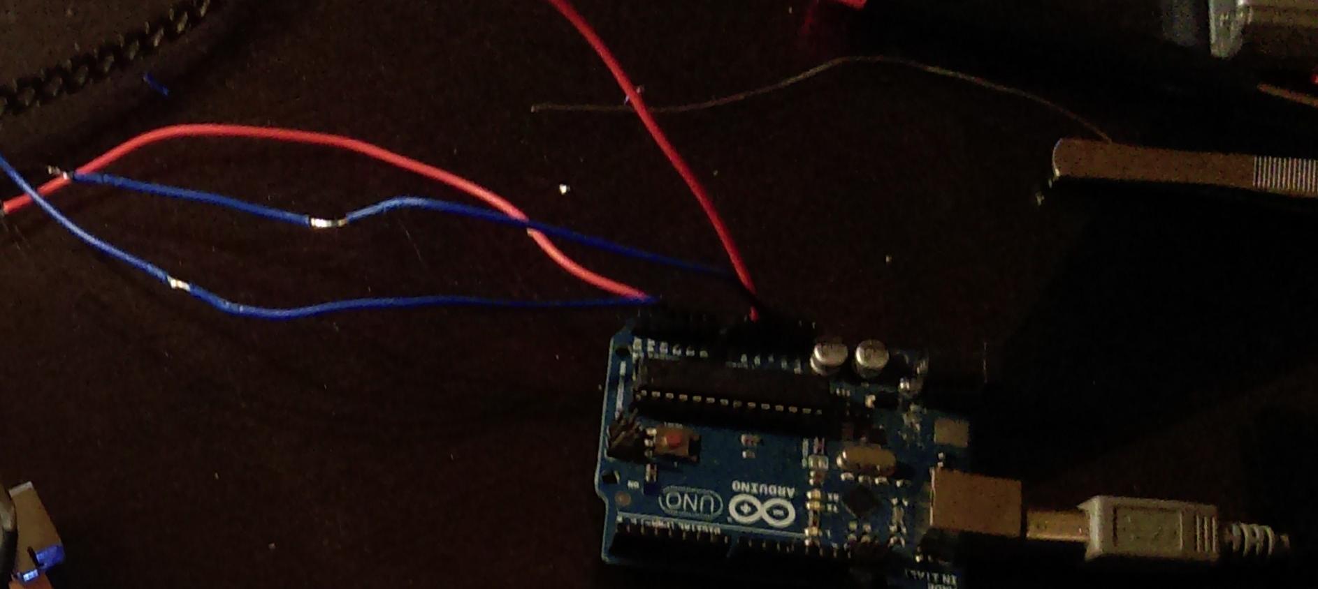
Connect to my Duino(wire it as you normal i2c):
My EDID dumped in Linux before proceding to flash:
    EDID:
        00ffffffffffff000daeb11500000000
        01160104902213780231d59f56589527
        15505400000001010101010101010101
        010101010101963b803271383e405a3c
        690058c21000001a9b2580ee70382340
        3523350058c21000001a000000fe0056
        434d3858024e31353648470a00000000
        000041319e0000000002010a20200005
    BACKLIGHT: 133
        range: (0, 976)
    Backlight: 133
        range: (0, 976)
    scaling mode: Full aspect
        supported: None, Full, Center, Full aspect
    Broadcast RGB: Automatic
        supported: Automatic, Full, Limited 16:235
    audio: auto
        supported: force-dvi, off, auto, on
  1920x1080 (0x4c)  152.5MHz +HSync -VSync *current +preferred
        h: width  1920 start 2010 end 2070 total 2226 skew    0 clock   68.5KHz
        v: height 1080 start 1086 end 1095 total 1142           clock   60.0Hz
Pasted in Deltacast EDID editor then modified Pixel clock from 152 mhz (60hz calculated in DTD calculator) to 209 mhz, you have to calculate by entering these from the upper code repecitevly from top to bottom
920x1080 (0x4c)  152.5MHz +HSync -VSync *current +preferred
        h: width  1920 start 2010 end 2070 total 2226 skew    0 clock   68.5KHz
        v: height 1080 start 1086 end 1095 total 1142
Export the modifications in EDID editor as hex, make sure you add 60hz(original mod) in block 3 so you can switch between 40 60 120, then using find&replace method modify the format according to the next step
Then modify the array in the code (acc to format, 0x and ,) upload to arduino: https://learn.adafruit.com/adafruit-tfp401-hdmi-slash-dvi-decoder-to-40-pin-ttl-display/editing-the-edid
I'v managed to go up to 120hz stable, yours may be different although the same model number...
 xrandr output at 85hz:
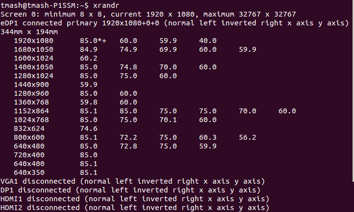
Had to reboot twice on Windows under UEFI boot manager in order to recognize the 120hz option, weird

Again, this is not a thorough guide, just sharing my experience. It went pretty straightforward, and simple as a typical EDID modding over VGA cable or DVI.
-
2
-
-
I guess its higher than 1.150
 Wouldn't be stable at 350mhz core clock... Would that damage the GPU? Thought temperatures are the cause...
I'm actually surprised by the temperatures i'm getting, I even used MSI overlay to monitor the frequency and the temperature, maximum today is 81...
I think it isnt worth the +50mhz, will drop it to 300 and +137.5mv...
-
 Is this dangerous? can i go any higher? its stable already... (max temp 78) thanks!
-
Thank you all!!
Worked perfectly!
Special thanks for svl7 for making this possible...
Just for future attempts:
Specs:
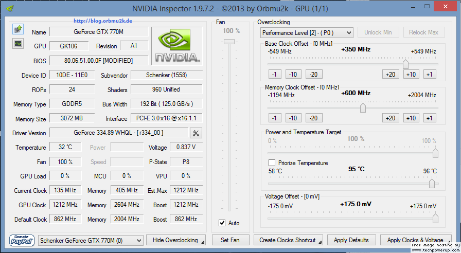
- NVIDIA GeForce GTX 770M
- Device ID: 10DE - 11E0
- Original subvendor and modded by Nvidia 770m - 80.06.51.00.0F 'OC edition' : CLEVO/KAPOK (1558)
-Before and after driver: nvlddmkm 9.18.13.3489 (ForceWare 334.89) / Win8.1 64
-REV: A1
-Stock VBIOS: 80.06.51.00.30 (P2303-1e00)
Now I got to fix the crashing problem when passing +130Mhz, cant raise the voltage in Afterburner...
EDIT: Fixed with the newer Nvidia Inspector and raised voltage by + 75mv and +200mhz core and memory
-
I tried the clevo 675mx vbios with my MSI once. It didn't brick completely but I couldn't use the card until I flashed the msi vbios again. So most likely flashing an asus or msi vbios on a clevo would do the same thing.
Thanks!
Hmm, there are 3 770m files, is the first one generic? no subvendor?
-
As seen in: Change Erazer X7813 Graphics Card - Page 2 - Medion - 4 Gamers Notebooks
The OP flashed from .30 to .11 MSI VBIOS...
I will try soon after the admin unlocks my user permissions...
Thanks again!
EDIT: haha, just got unlocked after posting this... Hopefully flashing it isn't risky... One more question, does the MSI/ASUS version works with CLEVO?
-
That's a good question, because your vBIOS file version doesn't match any of the 770M files on page 1 of this thread. I don't know which one is going to be compatible, either someone else can speak up if they know the answer, or I would google to see what other p150sm users have done re unlocked vBIOS flashing.
Thanks!
Is there any risk flashing the modified VBIOS with the 0F?
Can I recover it?
-
Clevo (or one of the heroes here) should seriously consider making a triple pipe CPU heatsink. I mean the 4900MQ at 4.2GHz can pull over 100W when running XTU bench. Even with the bottom cover off, using the P370EM CPU heatsink (which actually has 3 pipes) and forcing max fans I can just barely get the CPU to not throttle. Temps start out good but slowly creep up to 95C or above towards the end of the XTU bench.
Just imagine how much heat the 4930MX would generate if it was to run a stable 4.5 GHz on all 4 cores. 3 heatpipes isn't optional, it's a MUST.
True that, plus they should start using copper as the radiator material instead of aluminium....
-
Again, the fans are controlled by the EC. All Clevo SM series official BIOSes releases went with a change of the EC, different fan slope trigger and levels... Primamod bios lets you choose between the old and the new, newer would not trigger if the CPU temp is less than 50, if it reaches that then fans will turn on till it reaches 40C. Older: if CPU temp is more than 40, the cpu fan will always be on, but half the first level of the newer EC, more silent. I'm currently using the old EC, fan is on all the time overnight downloading torrent, while the newer one that came was off all the time, CPU idle 45C with IC diamond thermal paste, room temp: 24C... But I used the old one for school, since level 1 is noisy, fan vibration at some low rpm increments...
-
nice job! yeah, 24 , 60 , 85 Hz are the optimal settings for a synchronized ghosting, caused by our eyes retina response. Though depends on the screen pixel response too...
-
I'm new P151HM1 (ibuypower) user with GTX 560M is a beautiful laptop but I have 2 question very important for me.
I must decide if sell or take it for daily notebook.
1) FAN CONTROL, THere are possibility to control the fan speed o remap it directly on bios?
CPU FAN in idle with temperature around 35C is too much noise.
there are possibility to edit it on the bios to start on 45-50c, very low to 51-60, and more over 61C ?
2) GPU in IDLE. The fan speed is good, no noise in idle, (i have already set IC DIAMOND Thermal compound on CPU & GPU)
There are possibility to control the voltage ? I want to try less to default 0,82 volt.
I want a office profile with lower power consumption.
At the moment on idle with 1-4% CPU power consumption is aroud 45 watt.
Can anyone help me ?
Thanks in advance.
Checkout Prima Bios MOD, it allows you to flash 2 different profiles:
Oh and btw, fan is controlled by the EC not the BIOS, though, prima made modified the fan slopes of the EC firmware, always follow the tutorials...
-
Well, on my G46VW, brightness maxed out = colors washed out.
Now I have the Clevo P150SM, 4/10 matte
 barely reflects
 -
Hopefully Clevo would start making non-optimus setups for the next series like gt8xxm... Bandwidth bottleneck with SLI is expected...
-
Try to use XMP Profile 2...
-
Just use the aluminium foil trick on the radiator side...
-
Hey all!
Which GT770M vbios file should I use for Clevo p150sm?
my current stock bios is: 80.06.51.00.30 (P2303-1e00)
Thank you! much appreciated...

[4GHz+ i74700mq Hack or i7 extreme conversion] Intel Haswell CPU Microcode bug hack
in Overclocking, Cooling & Build Logs
Posted · Edited by tmash