


sskillz
-
Posts
98 -
Joined
-
Last visited
-
Days Won
4
Content Type
Profiles
Forums
Downloads
Posts posted by sskillz
-
-
Building a DIY eGPU adapter 8 - 20$ (ExpressCard to PCIe x1)
can you post more pictures of the build (adpaterto GPU connection)
-
When I made the x2 2.0 connection with port 1 WWAN and port 2 WLAN I only used TX/RX signals & GND from port 2. Plus setting port 1 @ x2.
Nothing more, nothing less.. I can't understand why it won't work.
I have been trying unsuccessfully to fix my PE3A to check myself but I failed. So I cannot be of any more help soon.
I assumed that the Modular Bay uses some kind of PCIe-->USB 3.0 card.There is no schematic that I could find for the USB3.0 Expansion module.
I got to that conclusion cause there are plenty EC to USB 3.0 adapters (found on eBay) using the USB 3.0 NEC/Renesas Chip or the USB 3.0 ASM1042. I own one EC to USB 3.0 adapter which uses the ASM chip and the tracks from the chip go to the PCIe signals on the EC slot. (I could upload a photo if you are interested).
I couldn't find any closeup to the connector online either. We could probably get a photo from someone who has already purchased it?
So maybe we need to enable USB3.0 mode with those mod pins (MOD_MD, MOD_SATA_PCIE#_DET), and I tried one of them. And those lanes are direct to CPU, can those be disabled by PCH for example?
If I didn't wreck the ODD port, I would have gotten USB3.0 module, it's probably PCI like you say and will provide the correct connector.
-
Is there anything else needed for x2 besides TX/RX and GND from module bay, TX\RX\GND from express card, and control signals from express card port that might cause it not to be detected/enabled?
like shorting PRSNT pins on 16x connector? using module bay PE CLK REQ or PE RST?
BTW how is the USB 3.0 module bay expansion module gets USB 3.0 from SATA/PCI-E? can we get a close up of the connector?
Dell Latitude E6320 E6420 E6520 E6330 E6430 E6530 E Bay USB 3 0 Expansion Module | eBay
-
Cool, I talked to nando in private about having a thin pcb/socket that sits between the CPU and the CPU socket to get PCI-E signals, and even about soldering to broken GPU Dell Inspirion 5110, and then this thread pops up. Good luck.
-
oh why didn't they add HDMI ports for another 3 lanes :|
-
There was a misunderstanding... I meant that my laptop works fine after the descriptor unlock. Not about enabling port 4.
heh, I meant how are you gonna test port 4. soldering? which bplus/GDC adapter? I guess will see anyway.
-
My laptop works fine after descriptor unlock. No problems at all.
I will be testing later today with my E6430's port 4...
awesome, how?
-
Dell USB 3.0 E-Modular Bay. Schematics show that port 4 goes to the modular bay. Since it is a shared product for Sandy Bridge (Latitude E6x20 laptops) and Ivy Bridge (Latitude E6x30) I assumed that the Modular Bay uses some kind of PCIe-->USB 3.0 card (There are NEC USB 3.0 drivers on the E6420 drivers page, Sandy Bridge did not offer native USB 3.0). Here is a shop that guarantees that it works with E6x20 and E6x30, which means that pcie port 4 is probably wired. Correct. Seems like it. Everything you say is as I see it on the picture. I will test on my E6430 tomorrow and get back. Just make sure that on your riser RX+- goes to pcie lane 1 RX+- (pins A21-22), TX+- goes to pcie lane1 TX+-(pins B19-20) as on the picture in the spoiler. I connected them the other way the first time I tried. If you tried and it still doesn't work, there is maybe something changed since the revision of the schematics we have.
Have you confirmed that port3 is set @ x2 mode? If you own Setup 1.x or any other program that can check, make sure that port 1 and port 3 are set @ x2 mode (port 2 WiFi would be disabled).
Yes that's how I connected it, and it's the same riser image I used. It seems the orientation for this schematic is as if looking ontop of a desktop motherboard female slot (the risers has VCC 12v (B1-B3, A2-A3) tied together so I assume its correct).
I have setup 1.x which confirmed its x2 on port 3 (I did it x2 on 1-4, 5-8).
maybe flashing back the restricted descriptor since it has strange effects on audio and stuff.
-
If you are interested since you unlocked your descriptor you can know unlock your ME firmware so it will allow BCLK OC. Check this thread out. Unlocking your ME firmware will allow you to OC your CPU up to 5%. I OCed an my i7-3630QM from 3.4GHz to 3.56GHz by setting BCLK @ 104,9. I will be posting more about this mod too.
Can you post the ME firmware, his guide isn't really clear.
-

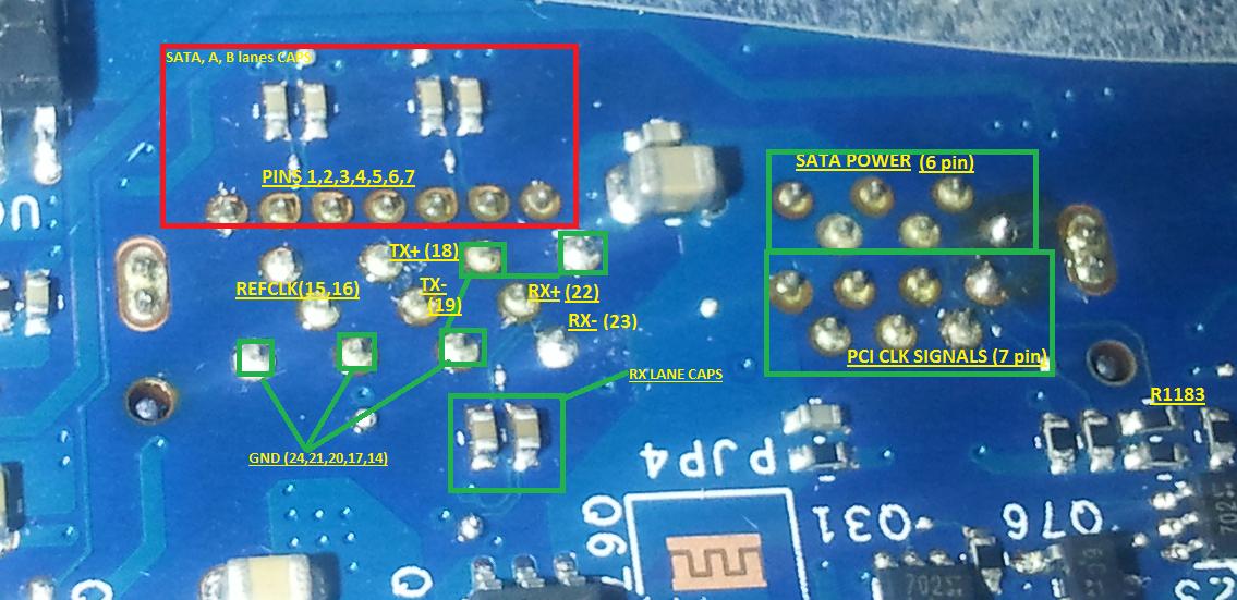
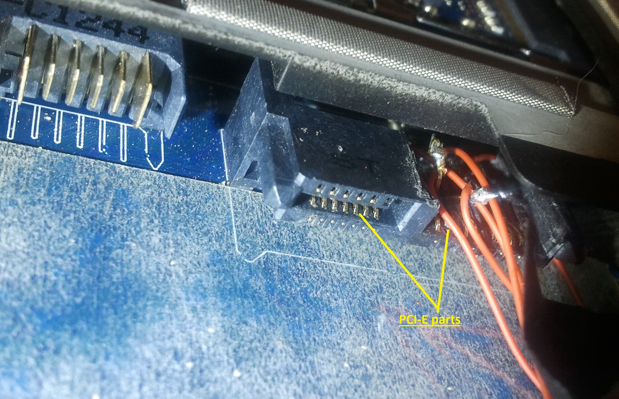
rightmost two pins of the SATA(?) power are GND, assuming pins 12, and 13. adding that pin 31 is connected to a 10k resistor (R1183), assuming the one in the picture which I measured to be 9.8K, and the resistor on its left also measured 9.9K going to MOD_MD pin 11 near the two GND I mentioned of SATA(?) power. So I'm guessing the count goes from upper part left to right 1 to 13 and then to lower part left to right 14 to 31.
So I assume I got the pins right.
Here's one of the connectors:
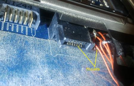
as you can see its has pins on top and pins on the bottom, its divided (top/bottom) like in the groups in the schematic JSATA2 with the same pin count. The right plug was a SATA L shaped female I destroyed. It's top was a normal SATA, it just has extra 11 PCI-E pins on the bottom that touch the plastic (don't connect) if its a normal SATA male connector since its they are one sided pins.
Why is there even PCI-E on this port? I can't find any dell equipment that uses the module bay for PCI-E.
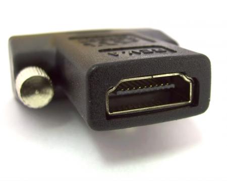
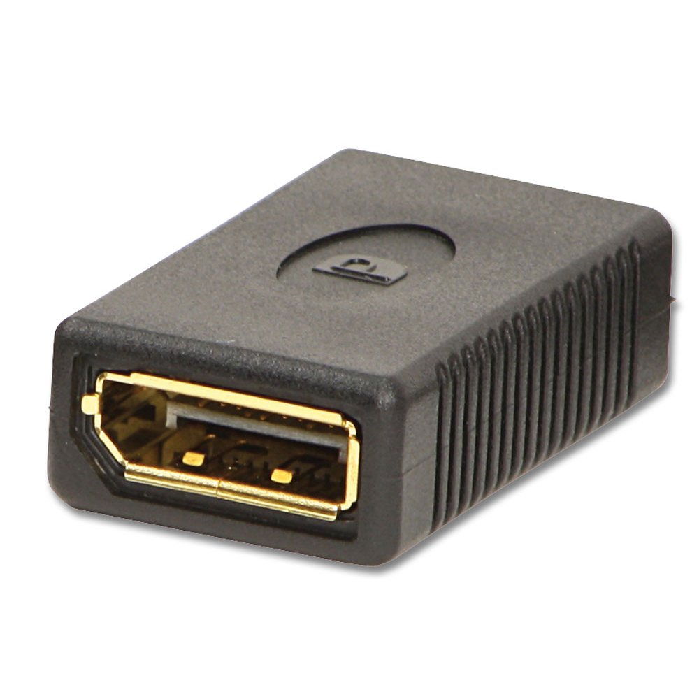
Maybe a disassembled displayport/HDMI connector (without the casing) might have the correct spacing and fit (might add some buffer as it seems a bit thinner), giving us a high speed shielded cable right to the port?
Display port

HDMI:
-
If you have a x2 capable PE4H or PE4C then wouldn't x2 1.0 would be easier using port3-EC+port4-module_bay. Your EC port would provide sync clock signals and need to wire only the 4 TX/RX wires + GND shields from port4. If were just testing port4 as a x1 link then need to wire through the CLK signals as well.
That's what I did, port 3-EC to PE4L and a RISER to the GPU, and soldered another lane of the riser to port4 module bay using a SATA cable (GND, RX, TX). [[bTW there are also PCI-E clock signals on the power part, again upside down of the normal power plug]]
I don't think that we need any of the two MOD_ * They both seem to be related with the USB 3.0 function of the E-module II.
Yes, but isn't that port combo a PCI-E + SATA, where does the USB come in.
Its possible I've got the pins wrong especially the pairs themselves but I was using a multimeter, the fact the RX lines has capacitors on them, and double GND between TX and RX which isn't between TX and CLK (and pin count).
I'll get a picture but I destroyed the port for easy access. Might not been the best soldering but its just a test.
And just to check, PCI-E connection is RX to RX (+ to +, - to -) and TX to TX right? not cross?
-
I can't get module bay PCI-E to work with express card using PE4L + RISER and show in GPU-Z.
Using the two GND lines and RX lane capacitors as "polarity" I think I identified which is which (GND, RX-, RX+, then two GNDs, TX-, TX+, GND, REFCLK-don'tcare, REFCLK-don'tcare, GND) from the other side unless they go in the connector not in this order, the schematic just shows it as a long port, so maybe the +, - are switched.
Then I soldered a SATA port I took from the disk drive (it has a SATA to flat connector inside) to the module bay, and using a sata cable to connect to the riser (RX+ to lane2 RX+, RX- to lane2 RX-2, TX to TX... and one GND which I soldered to one of the other lanes since they are all tied.
Soldering seems ok with multimeter and impedance also seems fine.
grounding MOD_SATA_PCIE#_DET pullup looks like just enables/disable USB3.0 somewhere, how is that related to SATA/PCI-E.
Maybe someone should try 1x from module bay first.
-
Great Work there! It seems like the iGPU model have the 92HD90B2X5 chip on the other side of the motherboard.
Added it here for future reference.

Is it possible to make the pinmod without taking apart the laptop?
Thanks for your insight
Probably from another 3.3v source, Its very difficult to short 5 and 9 because the chassis is in the way. But pin 5 has a unattached pad about a cm near it away from the chasis but is easier, so you can supply 3.3v there. I just used a 3.3v from the big resistor on the other side.
I wrecked the SATA/PCI-E Module bay to solder a SATA PORT (from the disk drive) to the ODD's PCI-E lane,
but I can't get 2x (port 3) enabled to test it, Maybe I need to supply "MOD_SATA_PCIE#_DET" or "MOD_MD" something?
Edit: Guess not had to shutdown not restart the laptop
 moving on to soldering a riser.
Don't know if it were mentioned but the module bay is a PCI-E/SATA combined port, its a normal SATA connection on one side and on the same connector above it is PCI-E.
If we can get a proper module bay connector (SATA like L shape connector but with 11 smaller pins above) we wouldn't have to tear it.
-
I've applied high signal on pin 5, then I wrote a modified flash with read access and write access set to 0xFF.
I restarted and now I can read the flash without applying high signal.
But I can't write again! It says Error 280: Failed to disable write protect for the BIOS space!
I can still read, but can't write even with applying high signal on pin 5.
Any idea what to do?
EDIT:
ok I can write just the DESCRIPTOR which I modified in hexedit
working! I've got a 2x port 1.
Thanks.
-
 1
1
-
-
@timohour,
hey I've got a iGPU e6430, but I can't find the 92HD90B2X5 chip. It isn't in the same place. any thoughts on where it can be? can you take a better resolution picture for the text/pins on it.
Edit:
found it, its on the other side, had to diassmble entirely to find it since I missed it at first. Its harder to reach but I'll try to reassemble (its a mess!) and using a pin.
thanks.
-
Just a quick update on my progress for the E6430 x4 project:
The E6430 arrived in good working shape, ready to be torn apart (evidently it's still under warranty)...
I contacted Bplus about getting shorter soldered cables with the PE4H and hope to get a reply soon. I realized that signal degradation could be a huge factor here so I looked into sourcing some PM030 and PM060 cables to test, along with an EC060. Once I learned the nomenclature I could actually communicate what I am looking for.
I will keep you posted once I get a reply. I contacted the Chinese support office, not sure if the Taiwanese office would have been better.
Thanks for your help Tech Inferno Fan and timohour this is going to be a lot of fun!
Isn't PCI-e lanes independent, each transmitters/receivers pairs should be the same length, but between pairs it doesn't matter if it within spec (https://www.pcisig.com/developers/main/training_materials/get_document?doc_id=6d37ec2f8543fc1f9d8ace6264d08b469f57e5f1)
What I'm saying is that if one pair connection usually works, two, and four should too.
Maybe a SATA cable will work for the other connections (just transmitter/receiver pair exactly as SATA).
-
-
Nice work, But that physics score :|
Are you gonna get a 15" or stick with this?
-
Hi guys!
Just thought it was time for me to show off my creation, haven't really presented it on the forum (except for my sign of course).
Here is a link to my gallery.
What you see is a 3d-desgined and printed enclosure with VESA mount, together with a GTX670 mini and EXP GDC v6.0
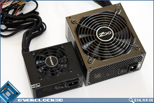
The 220W Dell PSU is modded with a power switch (5V for PE4L if needed) and custom made red cables.
I just hope this can be inspiring for others

Awesome!
-
I like the idea of the EXP GDC having an 8-pin 220W adapter, giving us the option of a portable eGPU without the large PSU attached to it.
Looking at this 24-pin connection on the PE4C v2.0 adapter, it looks like we are still stuck with bulky external power supplies.
Is there any chance that the DC port can reach 150W (enough for a GTX660ti)?
Wishful thinking.
EDIT: I found this adapter but am worried about its reliability.
maybe use a SFX PSU.

-
1
-
-
4k Should work fine if gpu supports it.
And about games, Which games? I've tried some 1440p games with my 290x.
Considering that about same game world is sent over the pci bus (in terms of draw calls, polygons, textures), unless the game actively sends higher detail/resolution for high resolutions (which more games this settings are detached from resolution) the difference is fill rate/shaders acting on more pixels intersecting the screen, and if fov is greater more polygons (less gets occluded and culled from the borders) will be visible.
I don't think it will affect bandwidth much.
So my guess is games that had a really high fps will work fine (you can probably disable AA) at 1440p, high fps will work fine in lower details. Basically the same performance drop ratio you see in desktop benchmarks.
4k Is a different beast and high end GPUs struggle with it. Bandwidth will not change much.
1080p game will look the same when the monitor is at such distance that the angular size (apparent size) is the same as your old/other 1080p monitor, but close up it will be blurry (depends on the game). Btw, You don't have to move the monitor much back to match the apparent size of a 24" monitor
I forgot how much is it but its about 13cm back...
-
-
You can't buy a G46VW with thunderbolt. They were never released. I had to source the motherboard from a company in Korea who had to use their contacts to find one. Also, it wont show up in the device manager unless their is a thunderbolt device connected as it disables the chip to save power.
As for your first request on the benchmark and temps. Sure thing!
cool, how did you know it exists?
-
Awesome. Your entire setup is sexy
Even your desk .Its a shame thunderbolt solution cost so much, it really shouldn't.
Can you test 3dmark11 3DMark 11 - DirectX 11 video card benchmark from Futuremark, you seem to have provided 3dmark (the cross platform one) instead.
And if you have bf3, bf4. Bf3 is much more bandwidth bound than bf4.
And is that a QX2710 screen?


14" Dell Latitude E6430 - Performance Upgrades and System Mods
in Dell Latitude, Vostro, and Precision
Posted
That would be great, but I can't send you a private message, your inbox is full
If its the one will the 3.3v pull up I tried shorting it to GND by inserting a large metal pin in the port (since there are two GNDs below that pin
and its the last pin), but maybe I didn't get a good connection. you should try again, update us