Arclite
-
Posts
19 -
Joined
-
Last visited
-
Days Won
1
Arclite's Achievements
Settling In (2/7)
14
Reputation
-
I may be late for this discussion as it moved to GTX 750Ti, but I want to post some link in order to provide more information on GTX 970 power consumption. So here is the link: Nvidia GeForce GTX Watchdogs Results Also check page 11 through 13 from that article. The link was taken from this post http://forum.techinferno.com/diy-e-gpu-projects/8304-gtx970-dell-da-2-test-results.html which contains useful information by itself.
-
US$189 AKiTiO Thunder2 PCIe Box (16Gbps-TB2)
Arclite replied to Tech Inferno Fan's topic in Enclosures and Adapters
This is great news. Also, does it mean that it isn't necessary to use a capacitor for the molex cable? -
US$189 AKiTiO Thunder2 PCIe Box (16Gbps-TB2)
Arclite replied to Tech Inferno Fan's topic in Enclosures and Adapters
I think it is safe to do that. -
US$189 AKiTiO Thunder2 PCIe Box (16Gbps-TB2)
Arclite replied to Tech Inferno Fan's topic in Enclosures and Adapters
What about the capacitor? Should a capacitor be used in this case? Soldering the molex connector onto the board means that the TB board will be powered by the molex. This means there are only two power inputs: the molex and the 6-pin pcie. This is the same build as the powered pcie riser build but without so much cables on the outside. That's great! -
US$189 AKiTiO Thunder2 PCIe Box (16Gbps-TB2)
Arclite replied to Tech Inferno Fan's topic in Enclosures and Adapters
@umax can you post a picture of HDPLEX power supply inside the Akitio Box? I'm curious what is the difference of size between the two and how much space is required for the HDPLEX to fit in. Thank you. -
US$189 AKiTiO Thunder2 PCIe Box (16Gbps-TB2)
Arclite replied to Tech Inferno Fan's topic in Enclosures and Adapters
Yes, this is the picture I posted some time ago, my first attempt to solve the soldering problem. Isn't it risky to solder the cables on those pins? -
US$189 AKiTiO Thunder2 PCIe Box (16Gbps-TB2)
Arclite replied to Tech Inferno Fan's topic in Enclosures and Adapters
Thanks for you input, trollinteemo. I thought too it lacks the clock and it may not work. Guess I have more evidence now that it won't work. I read your post and saw that you too want to implement a female-female PCIe riser and Im following your thread on new updates. Im curious how your enclosure will look and what components it will have. First, soldering something on the board will void the warranty and I was looking for a way to avoid it. That's how I came up with the female-female PCIe riser. Second, I don't know yet where to solder all power cables. There was some testing done by goalque which identified 7 pins near the Thunderbolt 4x board, but still for me it is not clear how to do it. Plus, there the capacitor, as you said earlier. Do you have more information on how to solder the power cables from the molex connector to the PCIe 16x board? Now that the female-female powered PCIe 4x to 16x riser doesn't work, the only solution is to solder the molex connector on the PCIe 16x board. @jacobsson If you use only the DA2 adapter to power the GPU, will you be using the original Akitio adapter to power the box? If so, there may be some problems with the GPU, as not all cards work only with 25W provided to the PCIe 16x slot by the Akitio power adapter. So far some EVGA cards work with this 25W limitation. What if the ASUS GTX670 mini card doesn't work with only 25W provided to the PCIe 16x slot? This question I asked myself for MSI GTX 760 ITX and started to look for a solution. Also, thinking about upgradability, I want to have the posibility to change the GPU in future. Some GPUs have twin 8-pin connectors or (6-pin + 8-pin connectors). The HDPLEX adapter provides the cables to power any GPU. If you're asking youself that another more powerfull GPU will not fit into the enclosure, you're right. If I choose to upgrade the GPU, I will either modify the front of the Akitio box to fit a longer GPU or create a new enclosure entirely. -
US$189 AKiTiO Thunder2 PCIe Box (16Gbps-TB2)
Arclite replied to Tech Inferno Fan's topic in Enclosures and Adapters
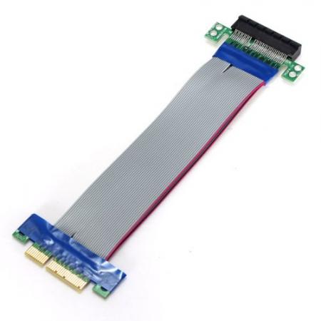
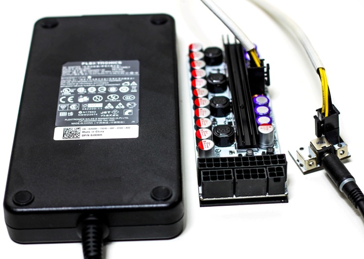
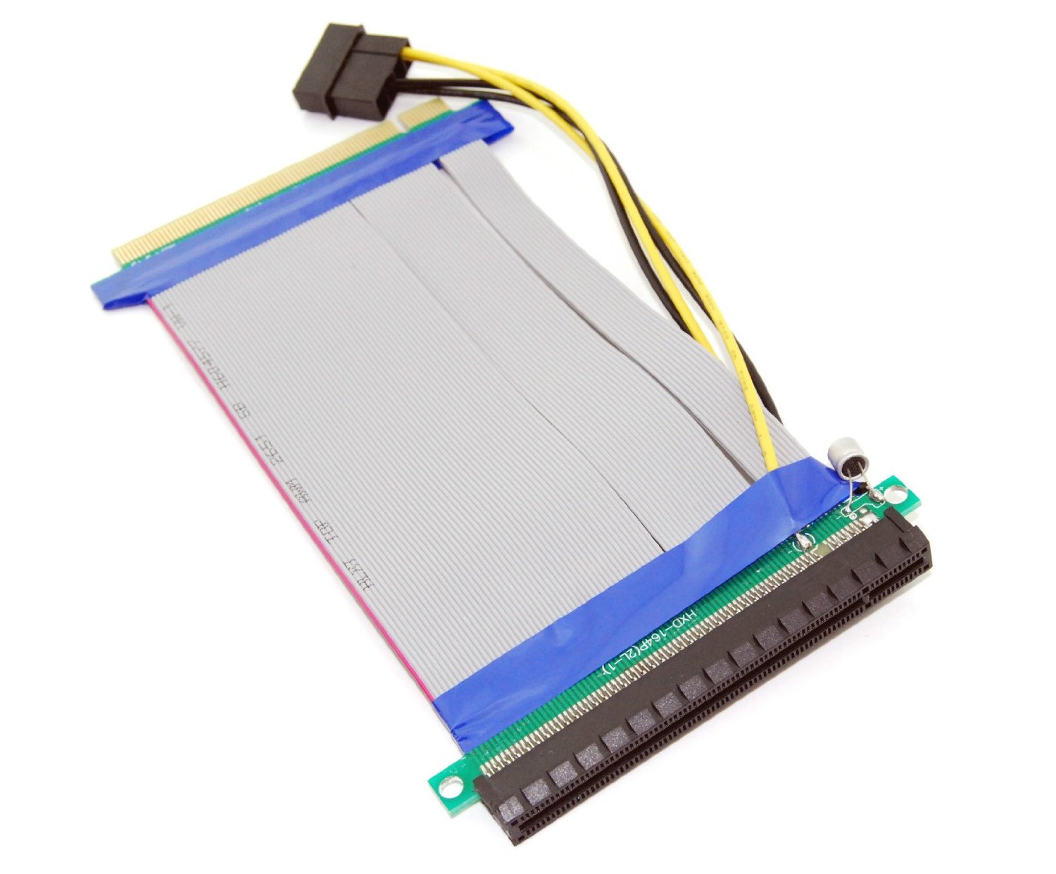
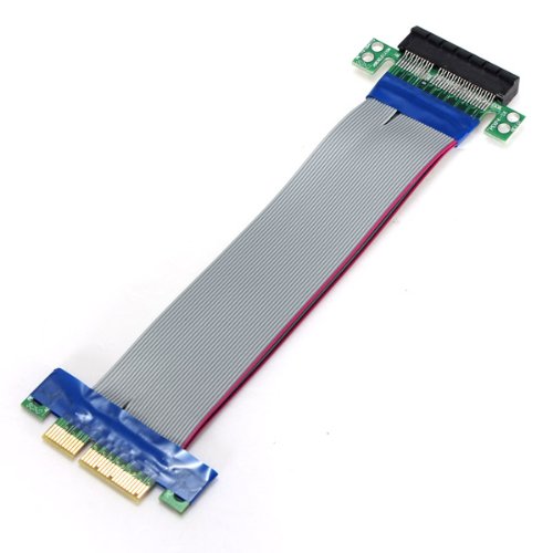
I want to create the following setup for the Akitio box: 1. Akitio enclosure without the PCIe 16x Board 2. The PCIe 16x board is replaced by a powered female-female 4x to 16x PCIe riser described here. 3. I need a molex connector for the powered PCIe riser, a 8-pin PCIe connector for the GPU (MSI GTX 760 ITX) and possibly a floppy connector for the Thunderbolt board. Im not sure if it will work as it wasn't tested by anybody, but in theory it should work. I want to use HDPLEX power supply because I need different types of power connectors. Soldering the Dell DA2 provides only one PCIe power connector so I can't use that. @reptilianbrain The setup I posted above doesn't have any cables on the outside, maybe it can help you in creating your setup for the Akitio box. -
US$189 AKiTiO Thunder2 PCIe Box (16Gbps-TB2)
Arclite replied to Tech Inferno Fan's topic in Enclosures and Adapters
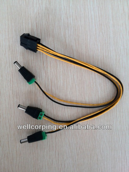
I googled a bit and noticed that there are these cables for 6-pin PCIe power There are 3 pairs of (12V + ground) barrel connectors. So this connector [ATTACH=CONFIG]12383[/ATTACH] should have 3 inputs in order to connect those 3 pairs (12V + ground). The PCI cable you show has yellow, black and brown cables. Im not sure how those 3 cables are connected to the barrel plug. It may not result in right wiring for 6-pin PCIe power. Do you have more information on the PCIe cable you found, the one with yellow, black and brown cables? Maybe a full picture of it?
-
US$189 AKiTiO Thunder2 PCIe Box (16Gbps-TB2)
Arclite replied to Tech Inferno Fan's topic in Enclosures and Adapters
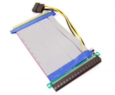
I'm not sure if your setup works, but I plan on using the setup below: You can find more details on this page. It provides all the ATX connectors including the 6-pin PCIe power input. Maybe it will help in setting up your Akitio box.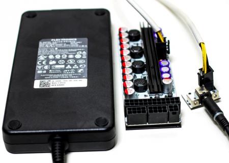
-
US$189 AKiTiO Thunder2 PCIe Box (16Gbps-TB2)
Arclite replied to Tech Inferno Fan's topic in Enclosures and Adapters
That is great news gualque, thank you very much for your testing It looks like we've got a x4 PCIe connector there, but just to be sure, let's wait for Tech Inferno Fan's conclusion -
US$189 AKiTiO Thunder2 PCIe Box (16Gbps-TB2)
Arclite replied to Tech Inferno Fan's topic in Enclosures and Adapters
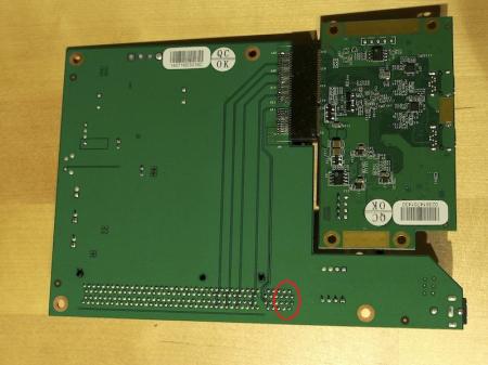
A powered PCIe riser has pins 1,2,3 on side B and pins 2,3 on side A connected to 12V. I illustrated in the picture below which side is A and which is B. Also pin 4 on side A and pin 4 on side B are grounds. Can you do a continuity test for all these pins too? Thank you very much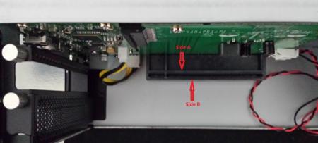
-
US$189 AKiTiO Thunder2 PCIe Box (16Gbps-TB2)
Arclite replied to Tech Inferno Fan's topic in Enclosures and Adapters
The only verification I did is counting the pins, there were 21 pins and as per PCIe spec, 21 pins equals a x4 connector. I understand that is not enough to prove it is a x4 PCIe connector. It proves that only it is a compatible physical connector with PCIe x4 but no an electrical too. Hope it is compatible electrically too -
US$189 AKiTiO Thunder2 PCIe Box (16Gbps-TB2)
Arclite replied to Tech Inferno Fan's topic in Enclosures and Adapters
According to the PCI spec pins 2,3 on side A and pins 1,2,3 on side B provide +12V to the PCIe connector. Pin 4 on side A and pin 4 on side B are ground pins. So, basically all +12V pins (2,3 side A; 1,2,3 side should be wired to the yellow cable on the molex connector and the ground pins (4 side A, 4 side should be wired to the black cable on the molex connector. That means we should identify where are these pins on the back side of the board. I highlighted the region where these pins should be. @Tech Inferno Fan Is this correct? Also, maybe there is another option. It is a little far fetched but I'd like to discuss it here. I'm thinking to create a female-female PCIe 4x to x16 powered riser. In order to do that I want to combine a male-female x16 to x16 powered PCIe riser and a male-female x4 to x4 PCIe riser so that the final adapter has only female-female connectors. Will such an adapter work ? On the AKiTiO board there are a lot of other components which I have no idea what is their purpose. Maybe there is a clock there, which provides the frequency for the whole board. If so, using a female-female adapter will not be possible as there is no clock. What are you thoughts about this?