


seefew
-
Posts
34 -
Joined
-
Last visited
-
Days Won
1
Content Type
Profiles
Forums
Downloads
Posts posted by seefew
-
-
i just know the ZOTAC GTX660Ti Amp!. Not 7xx nor 9xx.
The 660 have a short PCB.. But the metal cage around the fans exceed the size. As i removed this cage it fits into the Akitio
Greets
Mobil mit Tapatalk
-
Afaik there's no possibility to use Optimus in OS X.
May anyone knows more?
With my Macbook's i use the Akitio not to connect a Display.
I need the GTX only as a GPGPU.
With my iMac the Akitio works as eGPU with connected Display, and apart from the small startup issues, also very reliable.
-
Sorry for my late reply, i didn't noticed.
The Caps are soldered to the same interconnect like the PCIe wires. I think the Caps can also buffers here, but pls let me do a few test runs.
I'm away for a few days for relaxing. I'll do the tests next week.
Greets
-
Oh, guys,
a little crawl every day keeps you young and agile and it's as good for your Joints.

But toe training also
 :D
:D -
It should.
The PSU pulls up to 4A, the switch can handle up to 6A.
-
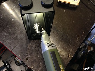
Hi Friends,
I don't wanna start a new discussion about this PSU. But what is a power SWITCHing unit without a switch, i thought? Without further ado, i took a switch and installed it.
And here's how it looks:

While it is very tight in the housing, but with a little tweaking, you can accommodate the switch.
The switch cuts both lines of the mains voltage, so it's ensured that even with incorrect house installation, the power supply is de-energized.
-
 2
2
-
-
I've added a 2nd 4 Pin JST housing. While software setup i've used it for to power the Akitio itself. In the finished build it was initially unused. I've read threads here and found ba10s118's instabillity Fix. According to this and because i don't like any parts outside the Case i've searched a possibility to add this fix inside.
Hope this answers your question
Greets
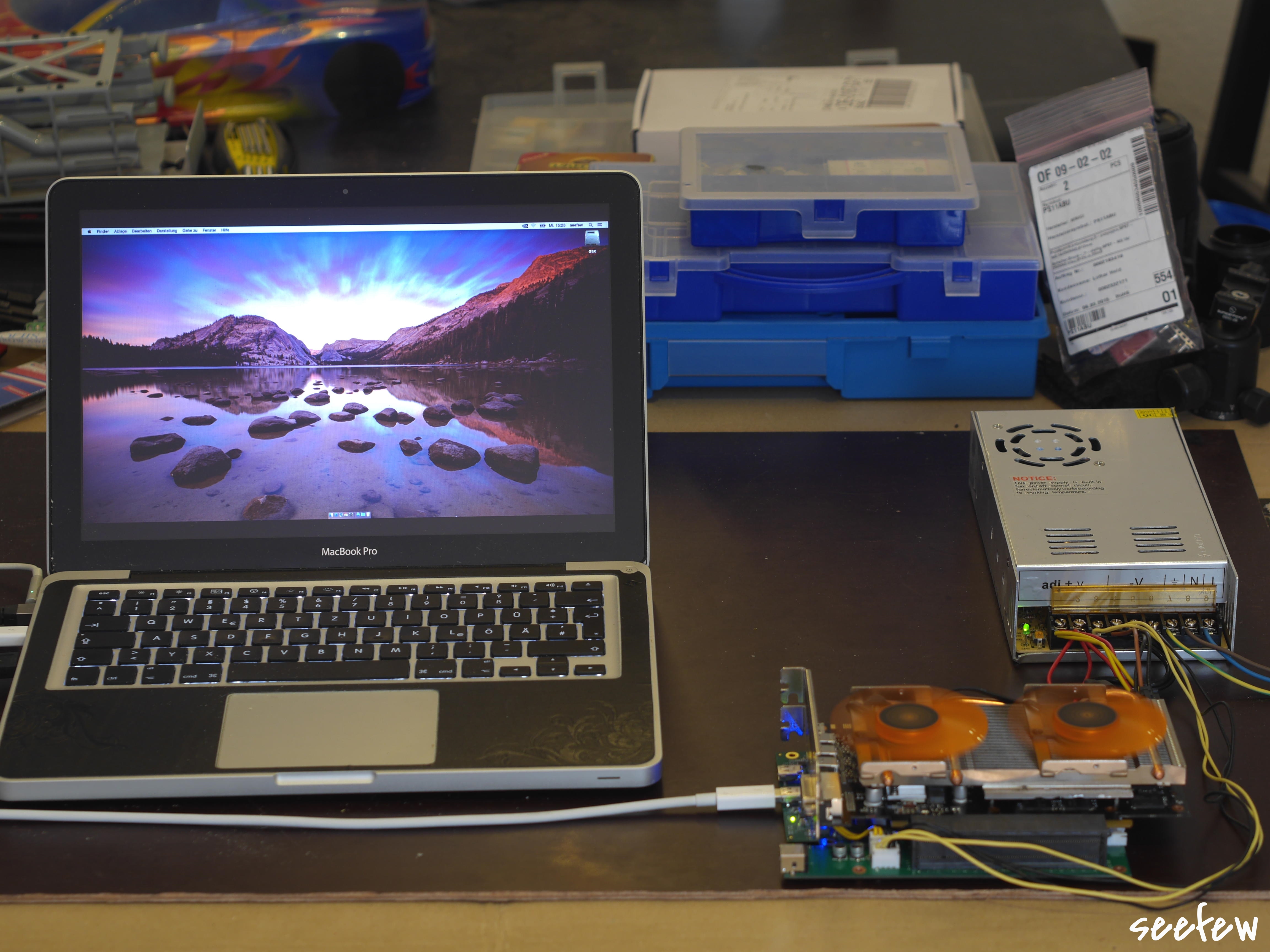
Added pic's of my computer desk and Heaven benchmarks in the first post.
-
Maybe a additional possibility for your frozen system from 6-13-2015.
Yesterday it was a very hot day.
I've figured out the following: during about 5 hours of 3D modeling only the TB PCB of the Akitio becomes very hot also, until the system freezes, while temps of GPU and CPU are in a regular range.
Greets
-
1
-
-
Thanks Dschijn!
But one thing is not clear to me:
Why the thread has been moved to "Provisional Guides"?
My build of the Akitio isn't provisional or "a work in progress" it's already finished and works right properly with my MBP and MBA.
-
Hi there,
at 1st i have to thank to that great Forum and all the members who helped and inspired me!
some of you have waited long time, thanks for your patience.
After several hours of soldering, drilling & painting i'm now proudly to present the results.
Although it does not looks like it take many hours of work but due i´m highly visibility impaired(my viewing range is about 2“) some simple things take much more time, therefore sorry if some img´s are creepy.
about the background why i build an eGPU / a GPGPU:
I own a Macbook Pro 13“(Early2011 CTO), a Macbook Air 11“(Mid2011 CTO) and an iMac 27“(Early2011 CTO), all with Sandy Bridge i5 & i7. Also i have a 3D Printer and a 3D Scanner.
For the most normal work their performance is quite sufficient, however, if more sophisticated models to be scanned or modeled, my Mac's poking often their performance limits.
Because of i've no desire to spend a few thousand bucks in new Mac's, I decided to build eGPU / GPGPU. eGPU for my iMac & GPGPU for my MB´s.
Hardware:
-
Computer:
- Macbook Air11"(4,1, CTO, [email protected], 4GB RAM, 256GB SSD) OS X Yosemite 10.10.3
- Macbook Pro13"(8,1, CTO, [email protected], 16GB RAM, 128GB SSD) OS X Yosemite 10.10.2
- iMac 27"(12,2, CTO, [email protected](soon replaced by [email protected]), 32GB RAM 128GB SSD) OS X Yosemite 10.10.3
[*]GPU´s:
- Gainward GTX970 4 GB GDDR5 (planned as GPGPU with my MB´s)
- Zotac GTX660Ti AMP Edition 2GB GDDR5 (planned as eGPU with my iMac)
[*]PSUs
- Dell DA02 (to use with GPGPU)
- industrial PSU 12V300W (to use with eGPU)
[*]and of course: Akitio Thunder2 PCIe Box
- Macbook Air11"(4,1, CTO, [email protected], 4GB RAM, 256GB SSD) OS X Yosemite 10.10.3
let's begin
@first i've dismantled the Akitio to get only the PCB´s and do the software setup on my MBP.
This step has been discussed in some Threads here several times, so I must do this not again?
If you wish i can do that of course.
(most of the Pic's linked to larger versions. Click on it for larger view)
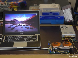
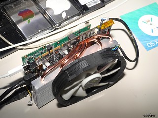
wiring on the fly for software setup
next step: electric/electronic mods
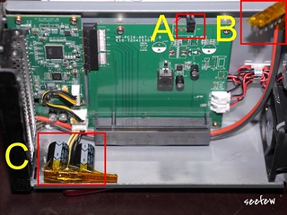
Description of mods:
A: added Connector for 2nd Fan
B: customized 6X2 PCIe connector
C: to prevent instability added 2x4700µF/16V
B & C have insulation of Kapton tape
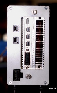
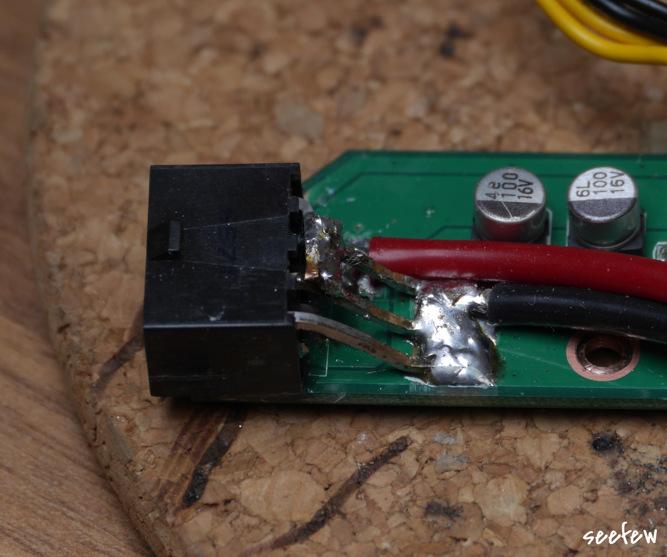
closer view to the current input
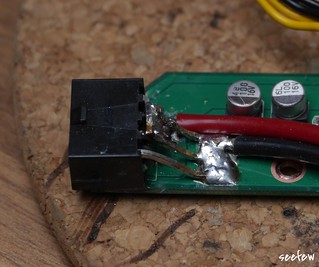
i've bought a Dell Optiplex including the PSU DA02 on eBay, desoldered the 4X2 housing from the PCB, desoldered the jack from the Akitio's PCB, take some 2K-glue and solder the new connector to the Akitio. For the moment the Remote pin is soldered directly to GND so the DA02 is permanently on if it's plugged in. I've replaced the wires from my provisional setup from AWG14 to AWG10, this should be quiet enough
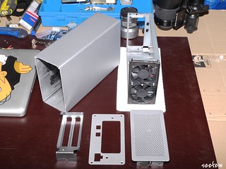
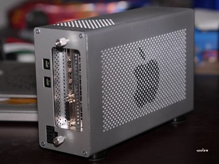
next step: Case mods:
increase the space above the PCIe
for better cooling i´ve opend the front of the inner sleeve and inserted a second 60mm fan
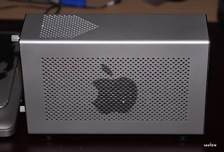
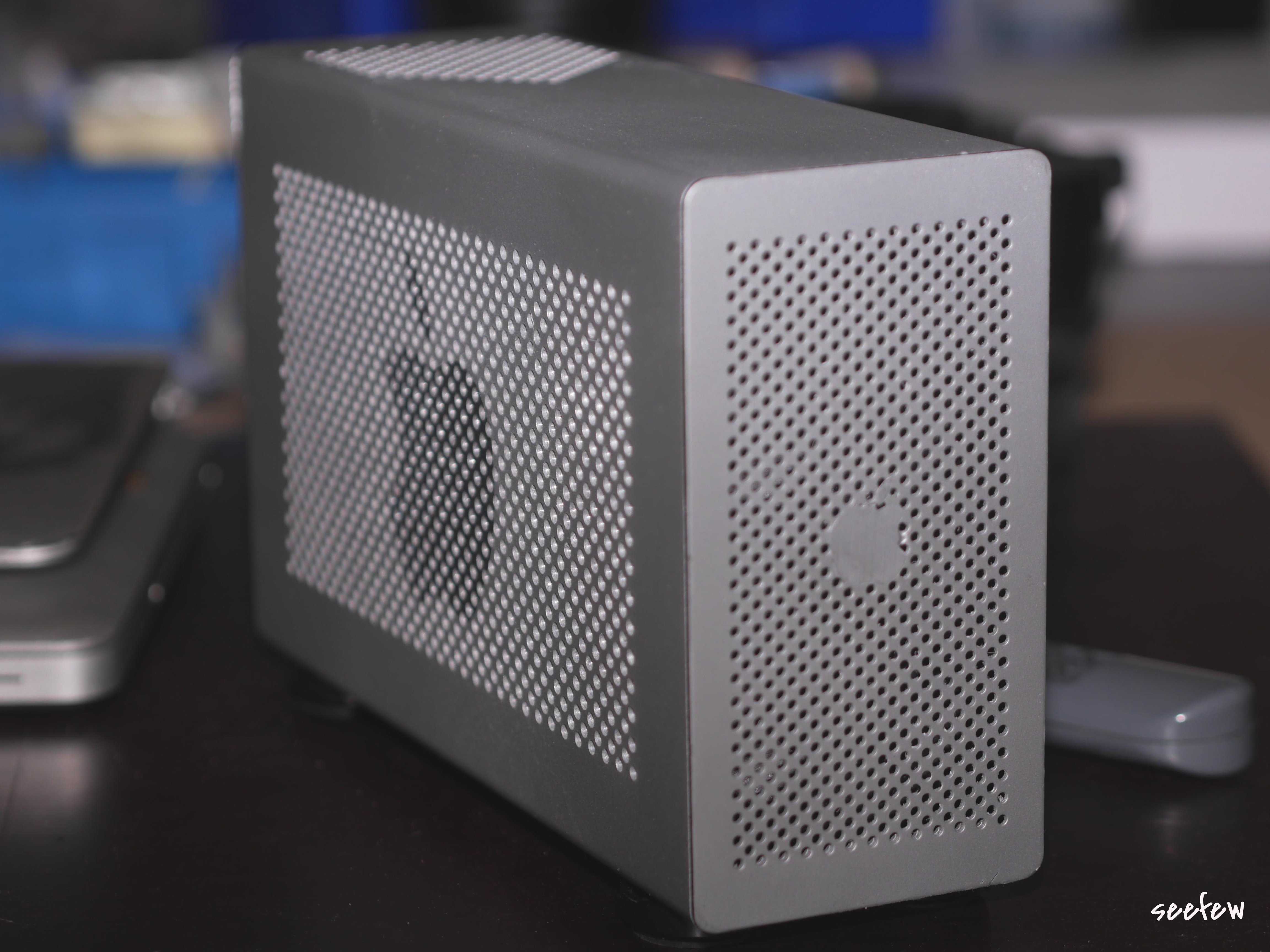
because of the black design isn´t my favortite design, i´ve firstly dismantled the housing completely and bring many many layers of argent and satin lacquer to the surface.
Look&Feel is almost identical to my Unibody Mac's:
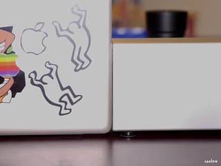
isn‘t it?
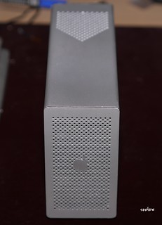
Despite of the second fan in the front, the ventilation was too low to cool down the GPU, when the housing is closed.
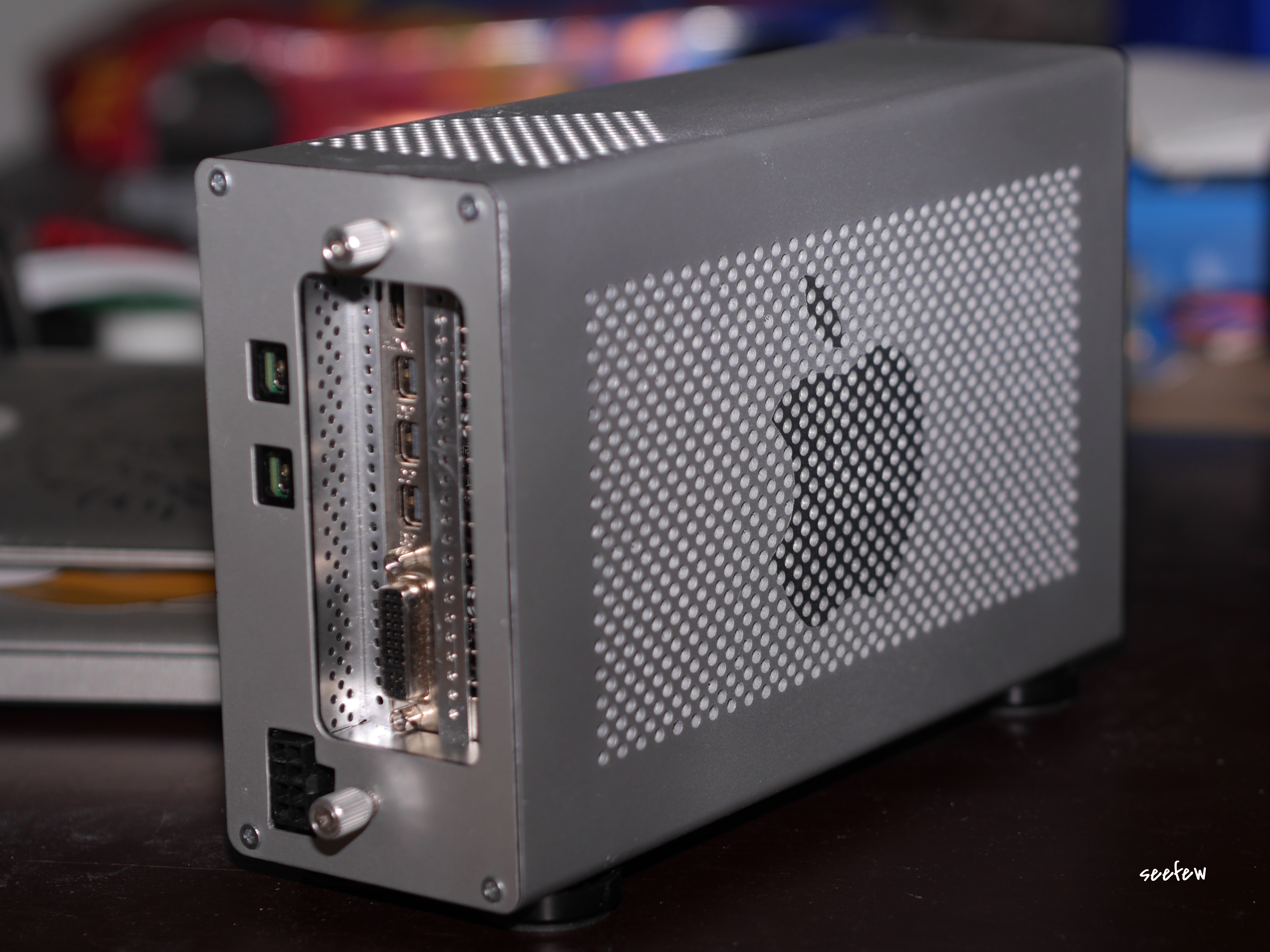
What to do, i thought? As well as my top fav design is the Mac G5/old Pro i take my drill and drilled overall 1150 3mm holes.
And this it is how it looks like after at least 6 hours of drilling and cleaning

The software installation went very smoothly both with the MB’s as well as with the iMac.
The MB's don´t have any problems during the operation. The used software recognizes the GPGPU and uses that also correct.
With my iMac I have several small problems with the eGPU.
I do not get it, not reproducible,
times it aborts the boot process and restarts automatically
times it aborts the boot process and remains frozen with a crossed out circle,
times it boots through normally.
When booted through normally,
times everything is OK,
times the screen settings where shaked up to settings i´ve never used.
Today i've made a provisional setup with the Akitio PCB's only and my Zotac GTX660Ti Amp!
There are much less problems during boot in contrast to the setup with the GTX970.
Here some img’s of it:
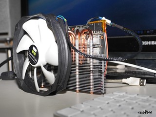
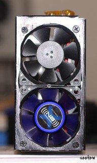
don't lol,
because of i've mounted the Zotac cooler to my GTX970 i've added an Arctic Accellero Twin to the GTX660Ti, atm i don't find the given fan so i connected a 140mm Thermalright
.So, that's it what I've made with the Akitio.
and finally:
Feel free to visit the album on flickr. There are some more img's
WTH stands aitAC for?
Simple desc: it means all in the Akitio Case, regarding to Dschijn
Hope you like my build
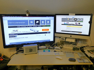
My desk, aitAC connected as eGPU to my iMac
Two Unigine Heaven Benchmarks eGPU(GTX970) vs. dGPU(Radeon HD6770M)
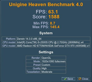 vs.
vs. 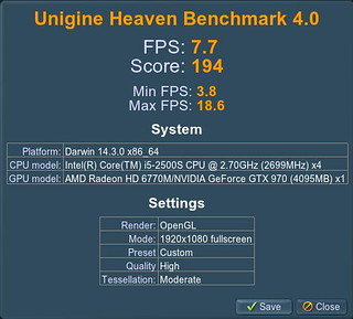
Greets
seefew
-
4
-
Computer:
-
also avail here: hit me
-
take a look at Morvs pic "egpuwiring.jpg".
Instead of the paperclip (red stripe) you can insert a switch. There's no huge load on it so you can use a small switch and thin wires
-
1
-
-
May you'll take a closer look to the temps.
My rooms are at the attic and during summer, temps rise often > 35° and more while it is winter temps below 15° in the rooms.
Times i've worked on huge 3D models eg full body scan or engines (> 1 million polygon) my iMac works quite fine in winter but freezes during summer.
-
1
-
-
Hi @ All,
i'm a little bit very curious, and I'd like to try something, maybe someone can help me.
I'm looking for the PCB layout and / or a Schematic of the whole circuit of the Akitio.
Thanks forward
Greets
-
......If I can plug into the WIFI PCIe port.....,
If I am not mistaken, the MBP's Wifi card has no standard mPCI, it's proprietary to Apple
-
I beg you.
Business or not, I mean, that's actually fraud with intend.
-
@Tech Inferno Fan: & @goalque:
Are there any known issues with backpowering the TB PCB while boot or while work?
-
I'm not afraid that the cable couldn't handle the current.Please take a look to the second picture of this Post
Maybe the pic haven't enough details, all 3 ground pins and all 3 12V pins from the DA02 are soldered to the PCB. The two cables are soldered to the PCB also.
At my 3D printers heated build area i use the same wires, while printing there are more than 20A (can't measure more than 20) of load and it works quite fine
-
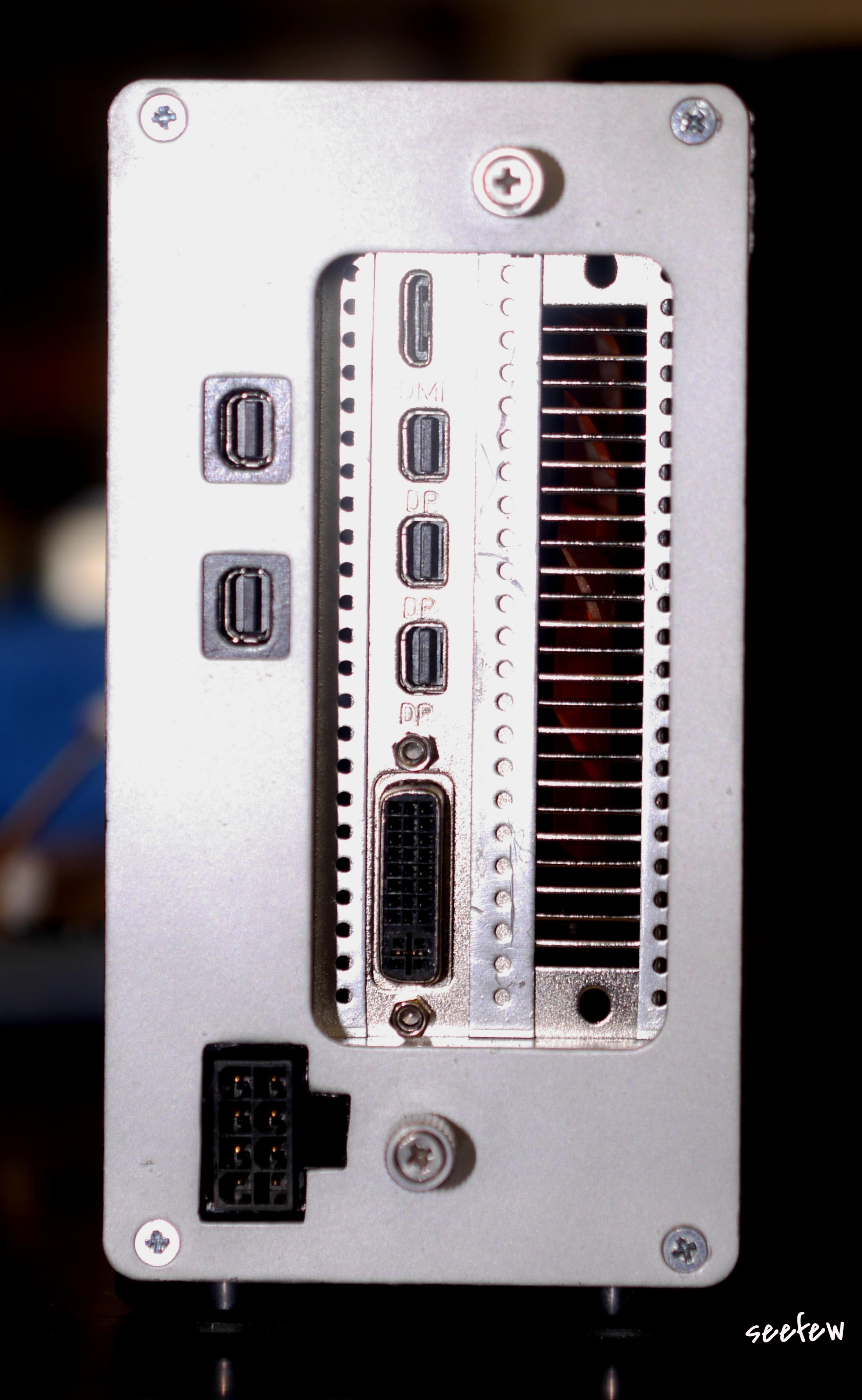
Due to the less space above the PCIe connector here's my way to avoid cable insulation damage and short circuit to the outer Case:


I've soldered the contacts and the wires (nearly ~AWG14) on a small stripe PCB.
If the plug is plugged in there's no risk of short circuit to the housing nor between the contacts.
-
2
-
-
thanks for your information, but I know this as well.
While were the last ~10 years was not as pronounced as in front, but more than 20 years in front i've had confected, sell and repaired PC's
Greets
-
1
-
-
If your PSU is a newer one, the main switch only the power voltage turns on, there is no other output as a control voltage.
You're have to do the paperclip trick to ensble 12V output.
-
as you say:
I have done the 75W bypass mod just in case.you meant this:
....... +12V spots are connected as shown with red circles, the yellow is not connected and blacks are ground.[ATTACH=CONFIG]14452[/ATTACH]
The three +12V corner spots is the easiest area, that's my latest mod with a single thick cable.
right?
You have also connectet the 4P JST between the PCBs and no contacts on the x4PCIe have elecrical tape?
Greetings
-
120W are 10A at 12V.
Maybe it works, maybe not.
On my Printer it dragged 10A the whole time.
I don't know the load consumption of the Akitio w GPU, is it always at 120W?
Maybe if you can get high quality jack & plug it works. Times ago i've found these but Instead of plastic they had ceramic insulation. Much expensive... about 30 Bucks per jack and the same per plug.
-
oh, i hope i'm not misunderstood. i've meant: it's not advisable to use a pigtail 4P JST - 6P/2x6P PCIe because the JST housing is risky to melt.
@Dschijn: A standard table i couldn't find right now. As far as i know these jacks / plugs can handle 12V / 5A.
In forward you should know, i do many things by t&e, so my experiences shows, however they may also handle up to 12V/7A w/o any problems for ~10h(then the print job was finished). As i pull ~4h 12V/10A on my 3D printer the insulation between inner and outer contact surface was melted
-
2
-


2011 11" MBA, 13" MBP, iMac + GTX970@10Gbps-TB1 (AKiTiO Thunder2) + OSX10.10 [seefew
in Implementation Guides - Apple
Posted
Sorry for my long absence, much other work in the meantime.
@toxec:
Only two 4700 mF capacitors because there're no more of them here, and a extra buy I'd no desire. Moreover several test runs and measurements have shown that they are sufficient.
@Charly:
Sorry, but my "Windows" are only for to let the sunshine in my rooms and look outside my house.

On my Mac's only run OS X
Greets
seefew
Mobil mit Tapatalk