Search the Community
Showing results for tags 'mod'.
-
Clevo W2xxHNx/W2xxHPx series Modded & Stock BIOS Note: This thread is no longer updated. You can find the latest info HERE. Notice: Make sure you have downloaded the correct Mod for your specific model and that the laptop's or a UPS battery backup is present during the update process. Disclaimer: I do not hold any responsibility for any problems that may occur by using the mods in a wrong way. Remember that you flash these at your own risk. I have personally tested the W25xHNx mod. Since the laptops mentioned here are of the same series and thus almost identical, you shouldn't face any problems with the rest of them. The same changes were made to all models after ensuring that their stock counterparts are identical to the tested W25xHNx laptop. Note: All mods contain both the Modded and Stock BIOS image files so that you can go back in case you want to. Use Mod.bat or Stock.bat at a DOS environment respectively. Check the Flashing Guide below for detailed instructions. W2xxHNx/W2xxHPx Mod Changelog: v1.2 Intel Sandy Bridge 206A7 CPU microcode 29 --> 2D v1.1 Intel Management Engine 1.5MB firmware 7.1.60.1193 --> 7.1.80.1214 Intel HD Graphics 3000 vBios 2170 --> 2171 Updated flashers to AFUDOS v3.07.01 and FWUpdate v7.1.50.1166 v1.0 Intel Management Engine 1.5MB firmware 7.0.4.1197 --> 7.1.60.1193 Intel HD Graphics 3000 vBios 2117 --> 2170 JMicron JMC25x Gigabit Ethernet Controller 1.0.9.0 --> 1.0.10.0 Intel Sandy Bridge 206A7 CPU microcode 12 --> 29 Removed redundant Intel Sandy Bridge 206A7 CPU microcode 14 Added support for Intel Core i7-2820QM ES/QS processor (W25xHPW) Fixed grammar mistake at Resuming from Hibernation image Fixed spelling mistakes at Advanced tab (Alart --> Alarm) Merged BIOS & EC firmware into a single image file Correct BIOS version & date reported in Windows Clevo W25xHNx series BIOS v1.01.07 & EC v1.00.06 [Mod v1.2] Supported Models (*): W251HNQ, W251HNQ-C, W255HN, W253HNQ1, W253HNQ, W258HNQ etc... Clevo W25xHPx series BIOS v1.01.07 & EC v1.00.08 [Mod v1.2] Supported Models (*): W251HPQ, W251HPQ-C, W255HP, W253HPQ1, W253HPQ, W258HPQ etc... Clevo W27xHNx series BIOS v1.01.05 & EC v1.00.04 [Mod v1.2] Supported Models (*): W270HNQ etc... Clevo W27xHPx series BIOS v1.01.05 & EC v1.00.05 [Mod v1.2] Supported Models (*): W270HPQ etc... Clevo W25xHPW series BIOS v1.01.05 & EC v1.00.04 [Mod v1.2] Supported Models (*): W251HPW, W255HPW, W258HPW, W253HPW1, W253HPW etc... Flashing Guide (Text & Video): 1. Create a bootable MSDOS/FreeDOS USB flash-drive using Rufus 2. Copy all files relevant to your model at the USB flash-drive's root directory 3. Plug the USB flash drive at your laptop's USB 2.0 port 4. Restart and press F2 to enter BIOS to make sure that you do not have any BIOS or HDD password protection 5. Restart and press F7 to enter the Boot Order menu at which select your USB flash drive 6a. To update your BIOS & EC to the latest modded version, type Mod 6b. To update your BIOS & EC to the latest stock version, type Stock 7. Follow the easy on-screen prompts to finish the update process 8. The first time after the update, the laptop will boot and automatically restart quickly 9. Press F2 to enter BIOS and Load Setup Defaults followed by Save Changes and Reset 10. You have successfully updated your BIOS & EC to the latest modded/stock versions (*) As shown at Clevo Bios Mirror and laptop Service Manuals Special thanks to Lordkag for the help and advice.
-
Hi @all, I have the HP Split 13 x2 (now with 8gig of ram and the i5-4200y). Apart from SSD, RAM, WiFi, is there anything that I could tune/mod/change to make it run faster? For example new coolers, better fan and with that an unlocked BIOS (no unlocked Bios -> no more power possible out of the small i5 ;-) ) Or even better a incredible cheap i7y ^^ Or something I didn't even think of. (What comes to mind is a different dock with more connection options or a new metal backplate) Please leave your comments, even if it is just to get me some ideas, something you already did or things you could help me with. Kind regards, Hermelinmaster
-
 I'm an architecture student going into College and I've been informed by my professors that I need to purchase a Quadro graphics card in order to run the hardware acceleration in the drafting programs we use. To me, this doesn't make any sense; why would I downgrade my already powerful GTX 780ti's (in three way SLI: overkill? Yes, I'm aware. But why the hell not?) for something not nearly as powerful, the Quadro 5000, and spend over $1000 on one graphics card? I've been reading about ways to crack the 660 into working, or at least reading, like a Workstation card, but is there a way to do it on something as recent as the 780ti? I'd still like to be able to retain the gaming capabilities of my PC but also, you know, succeed in college and not spend a fortune on another graphics card when I have 3 perfectly good ones in my machine already?
 -
I'm not sure what models this all applies to but: The alienhead on the back of the LCD is always white. It leeches of the LCD backlight and there is not remotely enough space to allow for a RGB system. Well, there might be, but it would be super tight tolerance and not for this particular system. I have some light gel sample thing for stage lighting. These allow an adequate amount of light through while changing the color of said light. One thing I love about this company is the overly cheesy names: Simply Mauvelous, Purplexed, Kablueie, Bluetylicious, Putting Green, Rust Assured, Just Peachy, Peach My Interest, Salmon"illa", Pink Pong, Pinkerbell. I personally used Bodacious Blueberry for this mod. Procedure:: 1. Rip off front plastic bezel. Start in an upper corner and work your way around. Pretty easy (Rider is watching you) 2. Pick your color samples: 3. I picked Bodacious Blueberry. Suigintou seems to like it as well. 4. Unscrew the LCD and make sure to pull away your webcam cable (it's stuck to the back of the LCD). Lay it down on your keyboard. You can test your colors now: Assortment of colors (Mauvelous, Neon Yellow, Diva Red, Bodacious Blueberry, Putting Green) 5. Determine how big to cut, I found out after my first cut, it's easier to just cram the light gel behind the silver reflective stuff, a dull xacto blade helps here: 6. Cut (this is too large to install in a easy manner, it ends up being about half this size - only need to stretch in the opening in one dimension either vertically too tall or horizontally too tall.): 7. Cram it in. The gel sticks a few mm over the top and bottom and is near flush on the left and right sides (in relation to the silver cut out): 8. Use a flashlight to test: 9. Slap it back together: 10. Enjoy. --- Pretty simple and quick mod. I did this spur of the moment while checking the pins on the LVDS cable to see if I could put a 1080p panel in here. It's a 40-pin 2ch 6bit LVDS connection. All 1080p panels that can fit in the m14x are 13.1" or smaller and 30pin LVDS. So a no go there.
-
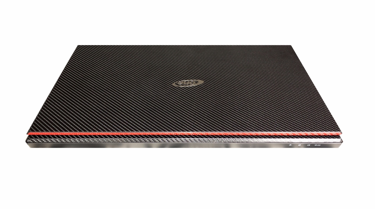
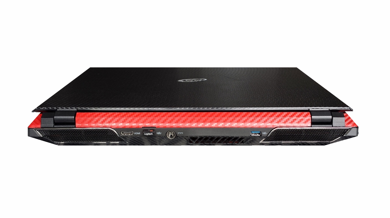
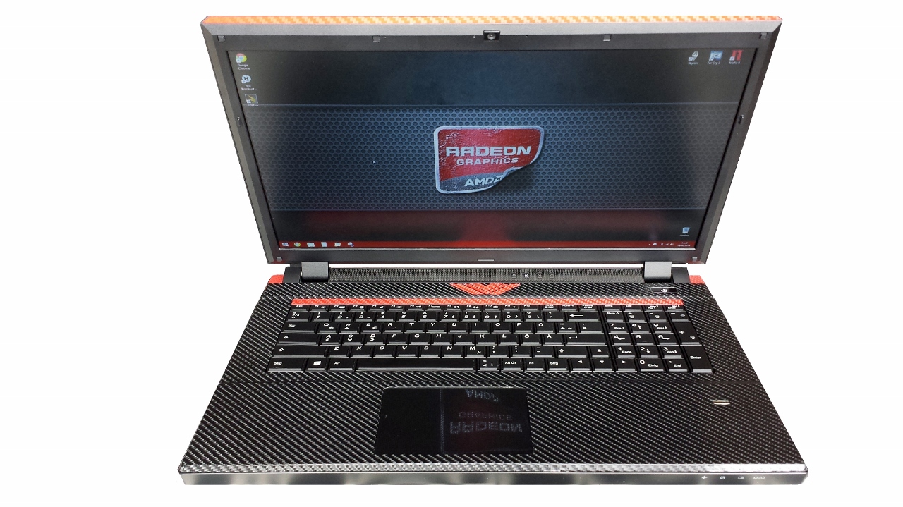
Hi guys! I just wanted to share my personal experience with the adhesive film. The equipment required is very simple: - Adhesive film (bought on ebay) - Hair dryer - Cutter - Felt wrapping squeege (bought on ebay) - So much patience (this unfortunately can not be bought anywhere ) The procedure is really simple and intuitive, the only difficulty is it does not create bubbles under the film, and be careful to trim the edges and corners. The end result is... Byee
-

[GUIDE] Dell 330W Power Adapter Mod for the M17X
Nospheratu posted a topic in Alienware M17x / AW 17
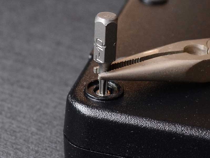
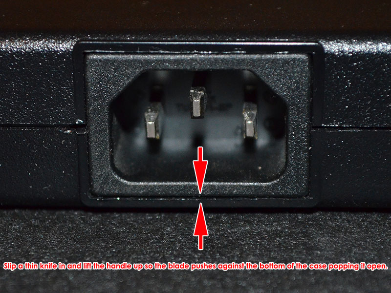
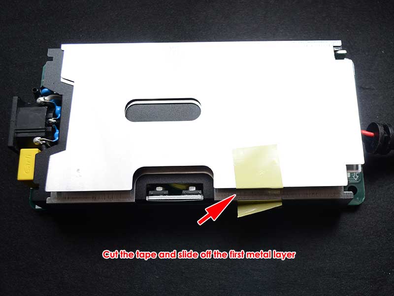
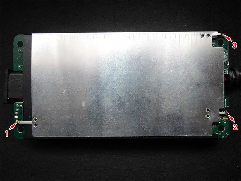
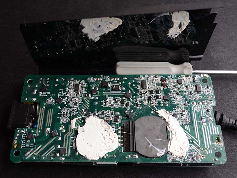
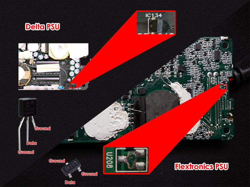
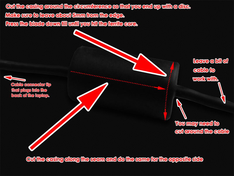
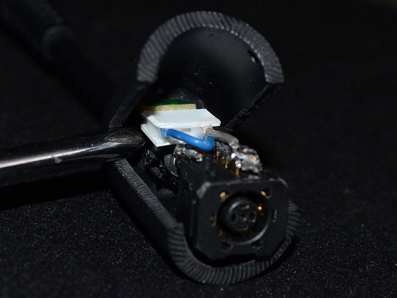
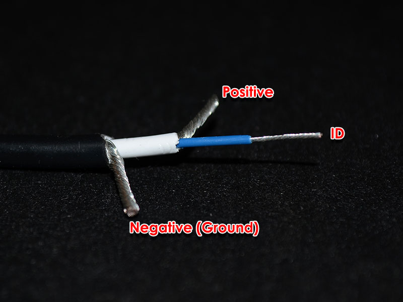
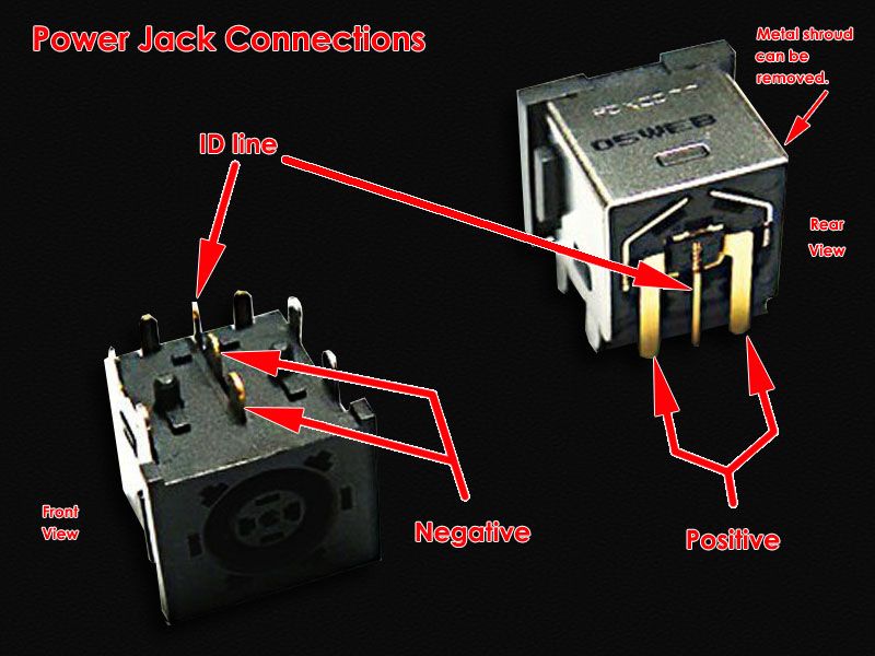
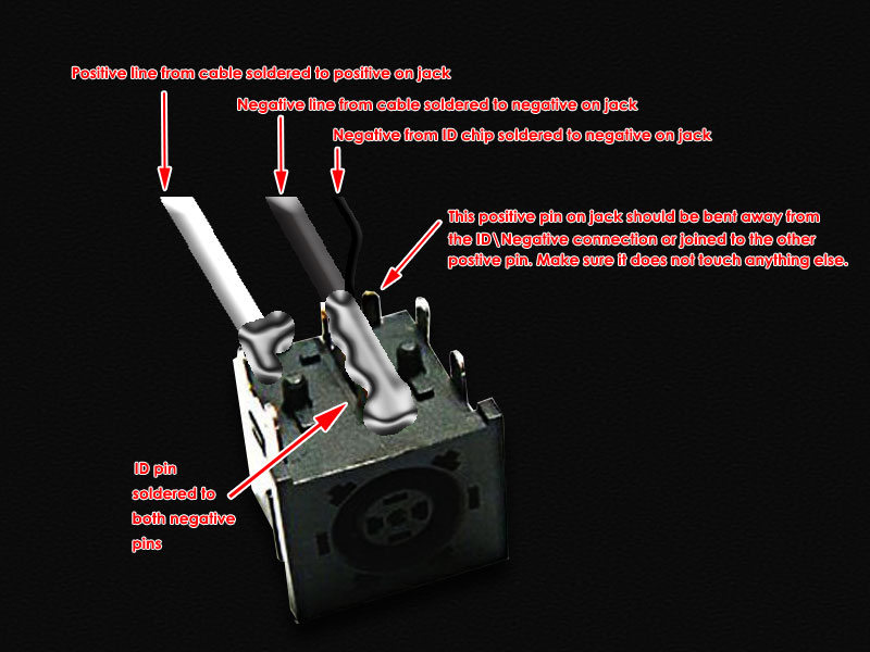
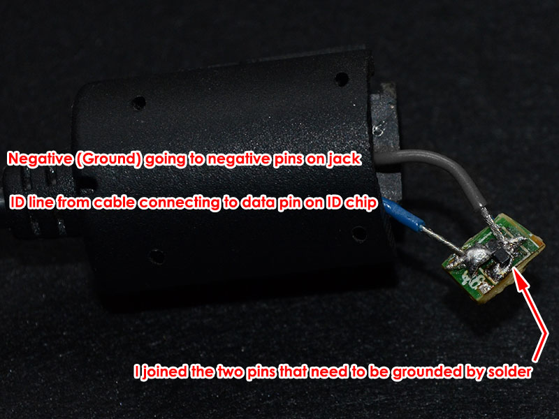
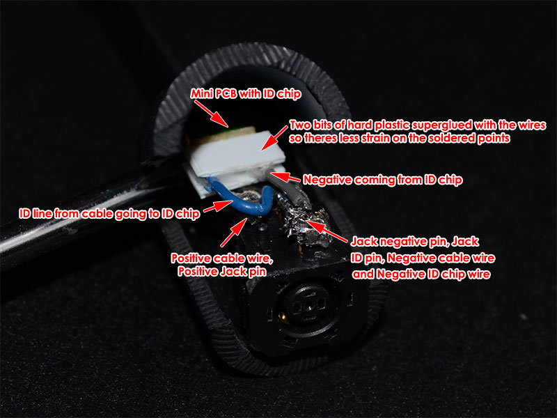
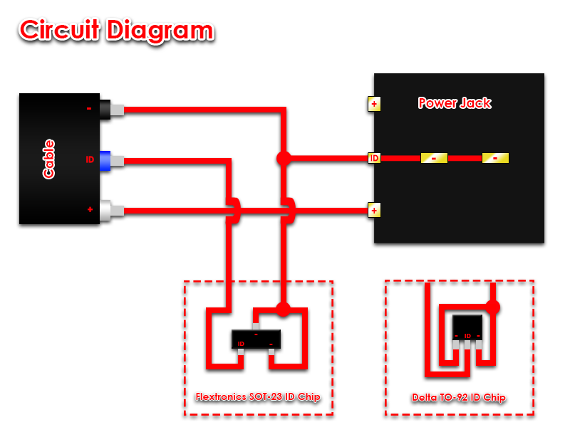
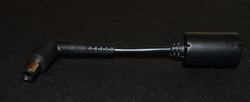
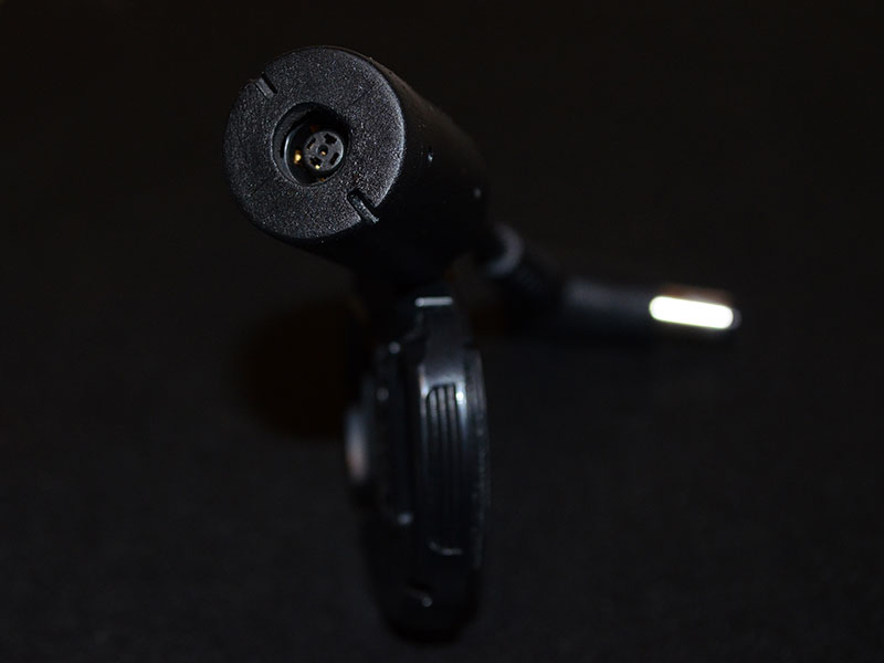
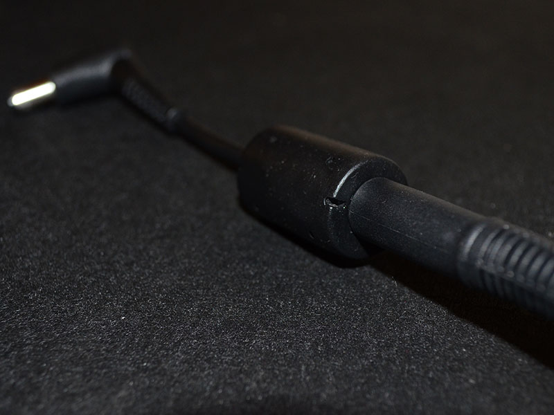
This modification involves going a step further than a straight ID chip swap between the 240W and the 330W. The reason I chose this method was, I did not want to perform the mod again in the rare case that the 330W died and I had to get a new one. In order to complete this mod, you will require the following items. 1. Dell 330W PSU (This PSU was built for the M18X and X51 product lines). Part Numbers: Y90RR / 5X3NX / F0K0N / XM3C3 / 331-2429 2. Dell 240W PSU (Either a Flextronix or Delta). Part numbers: PA-9E / J938H / Y044M / U896K / J211H / Y044M 3. Dell or HP standalone PSU cable/Connector. I used a right angle connector but any Dell/HP 7.4 x 5.0mm barrel connector will work. 4. M17x/M18X Power Jack. The part number for this power jack seems to be P01E. Look for the one that resembles the one used here. 5. Small PCB designed for a SOT-23 packaged chip. (If using the Flextronics 240W PSU). 6. Small housing (Optional depending on whether you would like to mod the ferrite choke housing) PSU DISASSEMBLY First we begin with the disassembly of the 240W PSU to retrieve the ID chip for our adapter. Since I had the Flextronics version some of these steps might not be the same for the Delta PSU. We start by lifting up the rubber feet on the bottom of the 240W using your nail or a flat tool. Underneath each rubber foot you will find a screw which you can go ahead and unscrew. One of the screws will be a tamper-resistant Torx T10 type, the difference to a normal Torx T10 being a small pin the centre so you would have to use a Torx screwdriver with a hole in the center. TIP: If you do not have this tamper-resistant screwdriver you can use a normal Torx T10 screwdriver but you will have to hammer down the pin at the centre of the screw slightly in order to get the normal T10 screwdriver to grip. Once you have removed all screws you will have to pry open the casing. I stuck a thin knife between the power plug and the casing to gently pry it open. The top half and bottom half of the casing are held together by interlocking clips. Twist the case a bit to get them to unclip. Then remove the PSU from the case. You will then be presented with the first metal layer which is held on by tape. Cut the tape and slide out the first metal layer. You will then see the second metal layer which is held in place by 3 points soldered onto the PSU PCB. It is indicated in the picture below. Desolder all 3 points and remove the second metal layer. The last layer is black and seems to be a type of flexible hard plastic. It will be stuck in place by white thermal stuff on the PCB, simply lift it and peel it away. Depending on whether you have a Flextronics or Delta PSU your ID chip will look different. Desolder this chip and keep it in a safe place (If you lose it, you have to buy a new 240W PSU). On the Flextronix PSU the chip is also stuck in place apart from being soldered on, so you have to work quickly heating the solder and pushing the chip away with a bit of force. To reassemble the PSU reverse the above steps. You can still use this PSU connected to the adapter with your M17X so it won't be collecting dust. THE ADAPTER MOD You will have to decide on whether you want to mod the ferrite choke housing into your enclosure or use a dedicated enclosure (small as possible as this circuit is tiny). If you are using a dedicated enclosure jump straight to the labelled wire photo to continue. If you would like to mod the ferrite choke housing continue reading. I did not take sufficient pictures during this portion as I was unsure if the ferrite choke housing would work. The rubber around the ferrite choke and the connector that I purchased was soft and very flexible which made it easy to work with. I used a knife and pressed against the rubber of the ferrite choke housing for a clean cut so that I could glue it back together. I cut off one end and then length ways along either seam of the housing making sure to leave a bit of extra cable. Here is a picture of what we’re trying to achieve with the cutting. You will then see the ferrite choke which you can crack with a hammer. Remove the pieces (be careful as they will be very sharp). Then the cut off the cable strain relief that's covering the cable with small wire snips. You will then see the cable which you can strip to positive, negative and the ID line. You will then need to connect those wires to the power jack. The two pins at the top are negative. The two pins at the back forming the shape of a U are positive and the pin at the back in the centre is the ID line. Solder the positive wire to positive pin and negative wire to negative pins as shown in the image below. The negative wire can be soldered to the negative pins and simultaneously joining the ID pin on the jack. The reason behind joining the ID pin to the negative pins on the jack is because we need to ground the ID line coming from the 330W in order for it to operate beyond its artificial 240W limit. Now all that’s left to do is connect the ID chip. If you have the Flextronics PSU the ID chip will be in a SOT-23 package and the Delta ID chip will be in a TO-92 package. The Flextronics SOT-23 package is difficult to work with and should be first soldered to a bit of PCB that had a SOT-23 package so that you do not break the legs off. I initially soldered the wires directly to the legs and moving it about in my "enclosure" to find the best spot to place it was too much stress on the chips tiny legs and they broke off... yes, all of them. Luckily I could still see a tiny bit of metal from each of the legs. I managed to salvage it by soldering it to a piece of PCB that I jacked from a broken mouse which had SOT-23 connections. The blue ID wire coming from the cable needs to be soldered to the data leg of the ID chip. Connect the remaining two pins from the ID Chip together and then to the negative connection on the PSU jack. Dont judge my pathetic soldering skills! Place your ID chip into the enclosure and test the adapter to make sure all your connections have proper contact. If it’s working properly you can close it up. I considered flooding the enclosure with silicone to secure the ID chip and its connections but I did not, as I thought it would be more work if one of the connections broke and I had to open it up again. You can do it if you like. I used a drill to make the hole at the centre of the disc large enough for the 330W connector tip fit through. I then stuck the enclosure back together using superglue along the sides and then attaching the disc. Add a bit of glue to the disc/jack so that the disc and jack are stuck together as well. This is so that the jack does not move when plugging the PSU connector tip in. THE COMPLETED MOD Pros/Cons over the ID Chip swap Mod Pros - Allows you to use any PSU irrespective of wattage as long as the connector tip is compatible with the power jack. - If the 330W PSU dies all you have to do is plug a new one in. No need to perform the mod on a new 330W. - No need to open up the 330W at all. - Your ID chip donor 240W PSU can still be used with your M17X by attaching this adapter. Cons - Allows you to use any PSU irrespective of wattage as long as the connector tip is compatible with the power jack (Could be dangerous with low wattage PSU's). - A lot more work compared to swapping the chips. Notes: I also had to trim a bit of rubber at the right angle connector for the cable I used as it’s a bit of a tight fit if you don't. The rubber around the connector did get a warm at the right angle after testing but it's being blasted by the heat of the CPU fan continuously so I don't think it’s the connector itself that's causing it. These cables are very short and should be able to handle the power easily. Since there are two positive terminals you will have to either split the positive wire coming from the PSU connector to each pin or join both pins (bend one pin over to the other and solder them together making sure to place an insulator to cover the ID pin) and solder the positive wire to a single point. Also worth noting is that this adapter mimics the original 240W adapter perfectly. So if you experienced the "plugged in, not charging" issue when connected this adapter will not resolve it (I still have to pop the battery and clip it back in to resolve). Credits: @imsolidstate, without his in-depth investigation this would have not been possible. His website detailing his investigation and the ID chip transplant can be found here and the subsequent update here. DISCLAIMER: Perform this modification at your own risk. I take no responsibility for any damage caused by technical error, user inexperience or stupidity.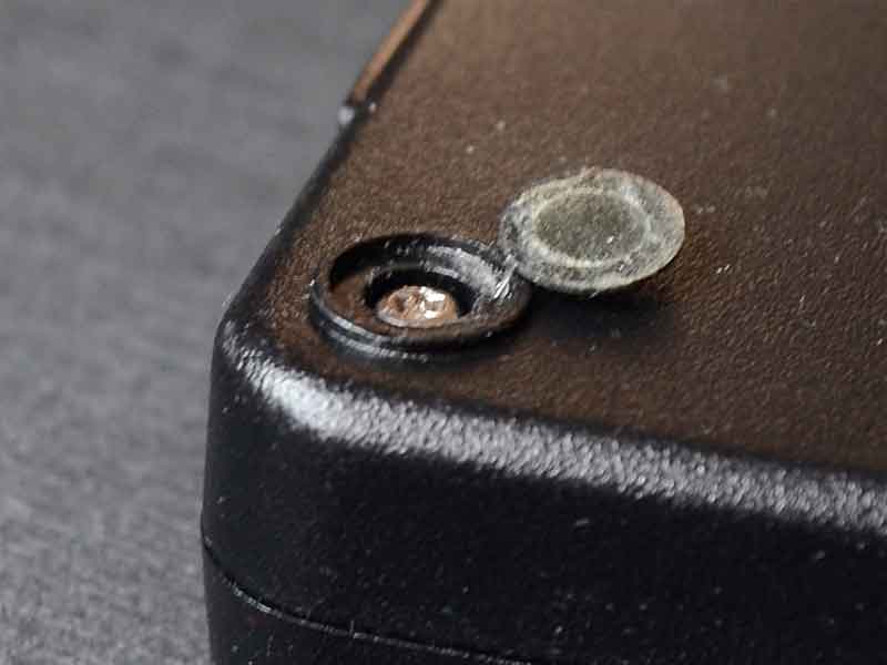


- 69 replies
-
- 15
-

-
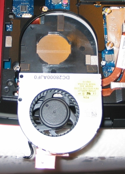
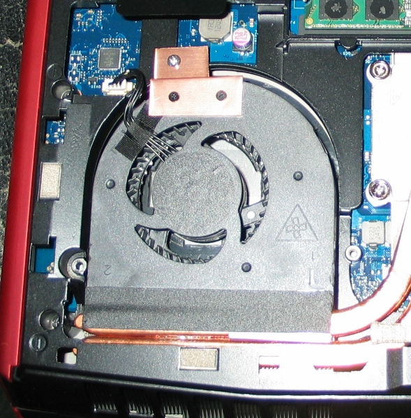
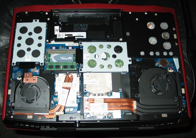
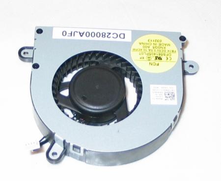
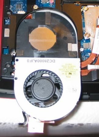
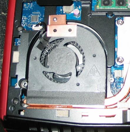
CPU Fan Upgrade Procedure for M17x R3/R4 (2.0CFM->10.4CFM!)<o:p></o:p> My original CPU fan was adequate (not great but adequate) fora 3740qm CPU @ 3.7GHz but when I upgraded to a 3920xm CPU and overclocked to4.1GHz x 4 cores, I needed more cooling - a lot more. Running a 60-second CPU stress test on all four cores in Intel XTU, with a 65watt CPU TDP programmed, and a core voltage of 1.351v, the difference is asfollows: · With original fan, system runs @ 4.1GHz for ~28 seconds before dropping to3.5-3.7GHz because of heat. On longerstress tests, it DOES NOT recover from this reduced speed state becausecooling is not adequate. Core Max: 92-95Celsius. · With this fan mod, system runs @ 4.1GHz for ~55 seconds before dropping to 3.7GHzbecause of heat. On longer stress tests,it DOES recover from this reducedspeed state and spikes of ~4GHz are seen for the remaining duration of thetest. Core Max: 92 Celsius every time. <o:p> </o:p> So here are the stepswith some pictures: 1. Procure an M14x R2 fan. It MUST be an R2 fan!! The fan blade design is clearly different so usemy picture as a reference. There are many eBay sellers, for example, selling the R1 fan as an "M14x series fan," implying that bothrevisions use the same fan - which is not true. The R1's fan has a 2CFM sticker rating while the R2's has 10.4! The markings to search for are: XN0G5 and/or DC28000AJF0. I got mine here: http://www.aliexpress.com/store/product/Cooling-Fan-for-Dell-Alienware-M14x-XN0G5/207462_647373968.html Note: Do not just swap the M14x's fan blade into your existing M17x fanshroud. I tried that first and it doesnot increase airflow. You need the newblade AND the new shroud for this to be effective. 2. Remove your original CPU fan. There are three screws that hold it in. Also disconnect its power jack from themotherboard. While you have access, youmight want to blast that exposed exhaust port with some compressed air to makesure everything is clean. 3. Notice the three mounting brackets that protrudefrom the sides of the fan shroud in the picture from Step 1. You'll need to cut them off so the shroudwill fit. I used a Dremel with agrinding wheel. There's also one smallblack screw in the corner with the yellow sticker. You'll need to remove it and grind down thatprotrusion as well. Save that screw forlater btw. 4. Make spacers/pads to hold the new fan up. The factory pieces will not line up so you'llwant something under the fan for clearance and to allow air intake from theunderside. I used small pieces of arubber material called Dynamat but padded mirror tape would work, as would manylayers of electrical tape placed on top of each other. It doesn't matter what you use - as long asit won't melt - and you'll want it to have a small footprint so it doesn'tblock airflow. I made my pads abouttwice the height of the factory material. Higher pads will allow for greater clearance and more air intake - justbe sure the fan still lines up with the heatsink and the case closes over it. This picture shows the three pads I made, and the fan shroud with its originalmounts ground off. 5. Create a mounting bracket to secure the fanshroud at the point farthest from the exhaust port. You could optionally fabricate mounts to lineup to all three screw threads on the case, but with my sturdy rubber pads andthe tape that will be included on the exhaust side if you buy your fan new, Iwas fine with only one new mount. Note: Leavethat tape covered until the end of Step 7. I used a thin piece of copper but any metal is fine. Bend the metal so it lines up to both the topof the fan shroud and the point above the screw thread on the case. Mark how it sits on the fan shroud and drill twotiny holes (1/16" bit) through the shroud-side of the mount. Now place the mount on the shroud using yourmarkings and VERY CAREFULLY drill further so that you have holes going throughthe plastic as well. Do not push hardand do not hit the fan blade within! Drill a slightly larger hole on the case-side of your mount where itwill line up with the screw thread. Thescrew you saved from Step #3 can be used for one of the shroud-side holes andwill not hit the fan blade within. Ifyou can come up with another similar screw, use it for the second hole. If not, you can take one of the other twofrom the shroud assembly if you want. It's also held together with clips so it won't fall apart. One of the three screws that held in youroriginal fan shroud can be used for the other (case side) of the mount. 6. Thoroughly blow off your new shroud inside andout with compressed air to remove any stray plastic scraps from the machiningprocess. 7. Fit everything up, making sure the fan sitsflush on all the pads you've made. Makesure it lines up with the heatsink and isn't too high or too low into thecase. Adjust pads as necessary. Once you're satisfied, screw in your mount tohold the fan in place. Now lift up thetape on the exhaust side (which should still be covered) and remove thecovering. Carefully fold the sticky partdown onto the copper heatsink pipes to secure that side of the assembly. 8. Plug in the fan's power jack. Again, ignore the connector being a differentcolor. It fits and it works withoutmodification or programming. 9. Close your unit up and enjoy!! So there it is! Let me know how this works out for you guys if you try it - and what you think about the procedure itself. Suggestions/questions are always welcome! * I obviously assume no liability if you break anything doing this. Informational purposes only, etc, etc, * This procedure replaces the M17x's original CPU fan (and fanshroud) with that of the M14x R2, and yields a greatly increased fanoutput. Both fans use the samemotherboard connector (ignore the color difference of the jack) so all that'sneeded here is to procure an M14x R2 fan, modify the mounting system a bit soit fits, and connect it up - and it works like a charm!

-
 First off, i'd like to thank Nando for all his work helping bring eGPUs to the masses. On to the post: The short of it: Where I once had a DVD drive that I barely used, I now have 3 low power USB ports and a convenient eGPU port. I’ve designed a caddy of my own in order to manage the new components. Full photo set: https://www.facebook.com/media/set/?set=a.193840844073776.17933.193579380766589&type=1 The long of it: This began as a simple 2nd HDD/DVD caddy swap. The more I thought about it however the more the fact that the HDD was physically smaller than the DVD drive, which ultimately meant unused space started to bother me. Incidentally I was also working on getting an eGPU set up but didn’t like the idea of having to take off the 2nd battery and bottom plate off each time I wanted to use the eGPU. The eGPU hardware connects via the mini PCIe slot where the Wi-Fi card is. So I decided to try to permanently embed the eGPU connection alongside a 2nd HDD where the DVD drive used to be. This threw a new wrinkle into the equation, since a permanent eGPU connection would mean disconnecting my wlan permanently. My solution was to go with a USB dongle for my wireless connection. New problem, where to find the USB connection….and where to hide the dongle. The last thing I wanted was to have it sticking out the side of the computer all the time. So the dongle also had to go into the caddy space. As to the USB connection, well there’s a wwan slot I never use right next to the caddy. While most wwan cards are physically a mini PCIe format and connection, they really work via USB. I found a card which breaks out the USB connection to flying leads (mentioned in the parts list below) and planned on using that to get my USB connection for the Wi-Fi dongle. New problem, most wwan mPCIe ports carry USB signal but not power. The port on the SB works like this. So where do I get 5v from? I could run the port power in parallel from one of the USB ports on the right side of the computer, but those make for some long leads and are difficult to run back to the caddy area. The only easily available source of power on the left hand side is the SATA connection itself. And that was my "aha" moment. I tend to use my laptop as a laptop when on the road but when at home it’s really working as a desktop. I’ve got a few USB peripherals and a screen I connect it to, plus the aforementioned eGPU. Ultimately I decided that I wanted more USB ports and a convenient eGPU port on the left side of the machine more than I wanted a 2nd hard drive. So I replaced the hard drive in the mod with a USB hub, with enough power to run the wlan dongle, an Asus Xonar USB soundcard, thumbdrives, peripheral dongles (Logitech universal, and Microsoft keyboard, etc.) It won’t power a HDD in a caddy however. I was also having some trouble fitting the hard drive in the original mod, but that’s because I was afraid of taking a dremel to the bottom case of the laptop (I’ve since worked through my fear, though I like the mod as is.) Things that still need doing: I still need to shave off a 1mm from everything, and I ended up warping the top case with one of my earlier attempts. I’ve revised the design of my caddy so that I can fasten the 3 screws along the face of the DVD drive which I had to forego with the old design. I also have to model this and get it 3d printed so it’s one integral unit. Also, it looks like the new version of the eGPU hardware (PE4L-PM060A) might have the mPCIe card and the adapter directly soldered to the mini hdmi cord, so I’ll have to revise the mod slightly. Even without revising the design, I have to go in there and clean up some cables now that I’ve had it in for a few weeks and know that it works. Things to watch out for: I somehow shorted the speakers on this computer, no idea how I did it but I’ve made my peace with it. Also I killed a couple of usb wifi dongles due to bad solder joints and shorts. (Will update with parts list soon…) Photos: Initial Testing: First stab at a mockup: Progress: End Result: Pic of the three usb ports with the eGpu port. Its the hole at the end, closest to the screen.
 -
Not sure if you guys know of this app that ejohnson from the NBR forums found on some russian site. It changes the AlienFX lights colour to match whatever is on your screen. It calculates the average colour that is shown on your screen and sends that colour to the alienFX controller to display. I've tried it and it works on my M17x R2 except for the power button and alienhead on the lid. Very interesting especially if you have alternating wallpapers with different colours Its a bit too distracting if you're watching a movie or playing a game though. Although it will should work well with say a fullscreen visualisation on your fave music player theHelios also from NBR set it up for us Alienware users and can be downloaded from his private dropbox below. http://dl.dropbox.com/u/1089880/Lightpack AlienFX.zip To see it in action check it on youtube The original thread can be found here.
- 3 replies
-
- 1
-
-
- alienfx
- ambilighting
- (and 3 more)
-
 I modded my CM storm SF-19 to filter dust and to vibrate less. The result turned out to be excellent. Q&A Q: Will this block my airflow? A: Not much, further down in the guide I am showing you the famous paper test after modification. Q: Does the anti-vibration mod work well? A: There will still be vibrations, but much less. What do you need? -Rubber tape -Electical tape -Mosquito net The dustfilter mod Step 1: Cut your mosquito net to fit the underneath of your cooler Step 2: Tape it to the bottom of the cooler The anti-vibration mod Step 1: Cut your tape to the correct size. Step 2: Wrap the plastic knobs with the rubber tape. Step 3: Reattach the fans to the grill step 4: Tape the mosquito net over the grill. Airflow is still strong As you can see in this picture, the paper is lifted quite high into the air. I am holding down one corner of the paper with a rubber hammock feet. Just as a safety precaution I am not responsible if any damage occurs The End
- 13 replies
-
- 3
-
-
- cm storm sf-19
- cooler master
- (and 5 more)