

Nospheratu
-
Posts
276 -
Joined
-
Days Won
6
Content Type
Profiles
Forums
Downloads
Everything posted by Nospheratu
-
Depends on your card. If its a CLEVO you can try the vBIOS's from the "forced" folder in the vBIOS pack in my signature. If its a Dell card try svl7's vBIOS he posted here.
-
Take a screenprint with GPUshark on the detailed view. That will tell us what voltage the card is really running at those clocks. Some cards refuse to change voltage and are "stuck" at default voltage or lower irrespective of what vBIOS you flash. Good news is you can fix that by flashing a modded vBIOS with multiple values in the voltage table changed to the voltage you want so the card is forced to run at that voltage.
-

[M17x R2] with AMD 7970M CrossfireX
Nospheratu replied to StamatisX's topic in Alienware M17x / AW 17
I had a look at your GPU-Z screenprint on NBR and your default clocks at set to 1000/1400... which is a massive overclock from the stock 850/1200. Did the card come with these clocks or did you flash a custom vBIOS? My cards with the same clocks and 1.025V hit 93C on the primary and 83C on the secondary playing Crysis 3 so your temps seem normal for that overclock. As you're running a CLEVO card take a look at the CLEVO vBIOS pack, the links in my signature. You can flash the stock version which is included in the pack but I suggest flashing the 0.975V version as the card is perfectly stable at that voltage and temps are reduced a lot. If you can take a screenprint with GPUshark on the detailed view. This will tell us what voltage your card is using for those clocks. -
[GUIDE] AMD HD7970M with Enduro vbios modify and flashing (For P1x0EM and etc)
Nospheratu replied to Aikei's topic in Clevo
I normally check with Checksum-16, it gives me the same result as ATIflash. -
Welcome to T|I @PC-Konsulten.se edit: See @Prema's post below... seems I was talking nonsense
-
[M17x R2] with AMD 7970M CrossfireX
Nospheratu replied to StamatisX's topic in Alienware M17x / AW 17
Congrats @nitsun69 !!! Has it arrived as yet? Welcome to T|I @Chris9966 If you boot with the 7970M and let it run for a bit do you hear the Windows logon sound? I'm not certain as to why it stopped sending signal to your laptop screen but you can check if its working by using an external monitor plugged into your VGA port. If you do get picture you might need to flash a compatible vBIOS. Do you have a Dell or a CLEVO 7970M? If you are unsure you can post a picture of the back of your card here and we will be able to tell the brand as well as what vBIOS its probably running currently. -
M17x (All revisions) OSD Icons by Nospheratu
Nospheratu replied to Nospheratu's topic in Alienware M17x / AW 17
@edrick002 on Windows 8 users are reporting that the default Windows 8 OSD displays instead of the Alienware OSD. I'm not sure if that was Alienware's intention or its a bug. The Alienware OSD is set up to automatically run at login so there's nothing you need to do to start it up. -
[GUIDE] Dell 330W Power Adapter Mod for the M17X
Nospheratu replied to Nospheratu's topic in Alienware M17x / AW 17
Thanks @flingin now get to work!!! -
[GUIDE] Dell 330W Power Adapter Mod for the M17X
Nospheratu posted a topic in Alienware M17x / AW 17
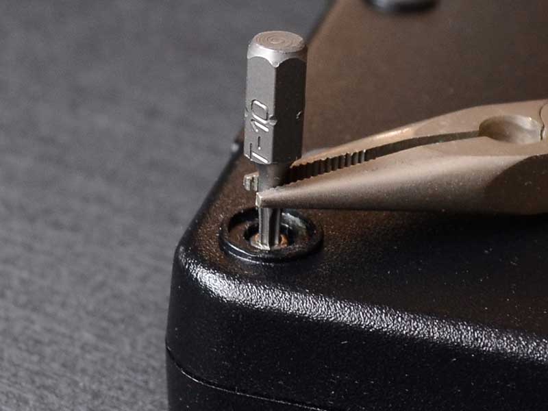
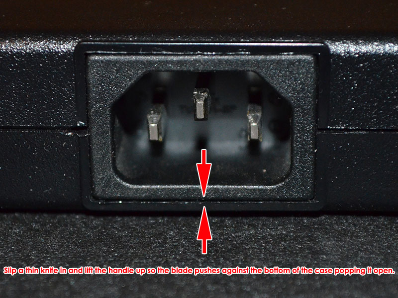
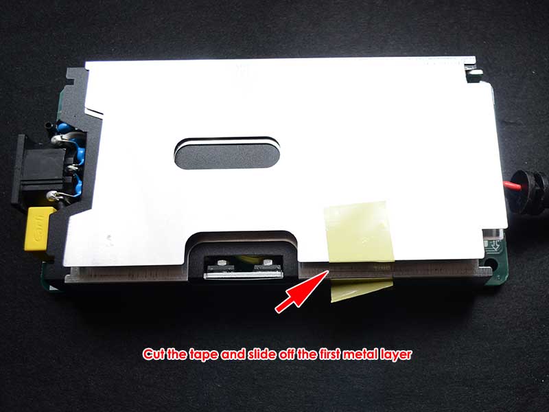
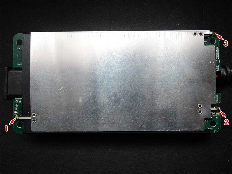
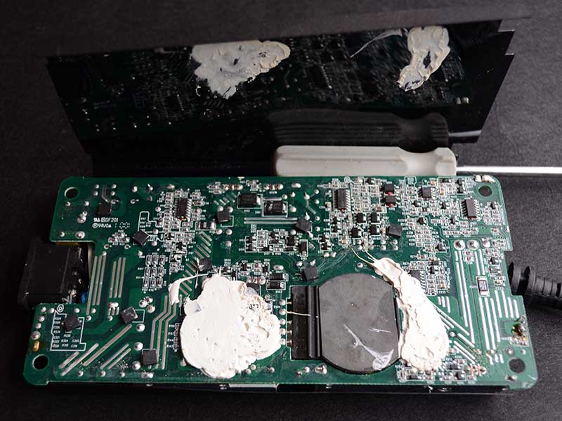
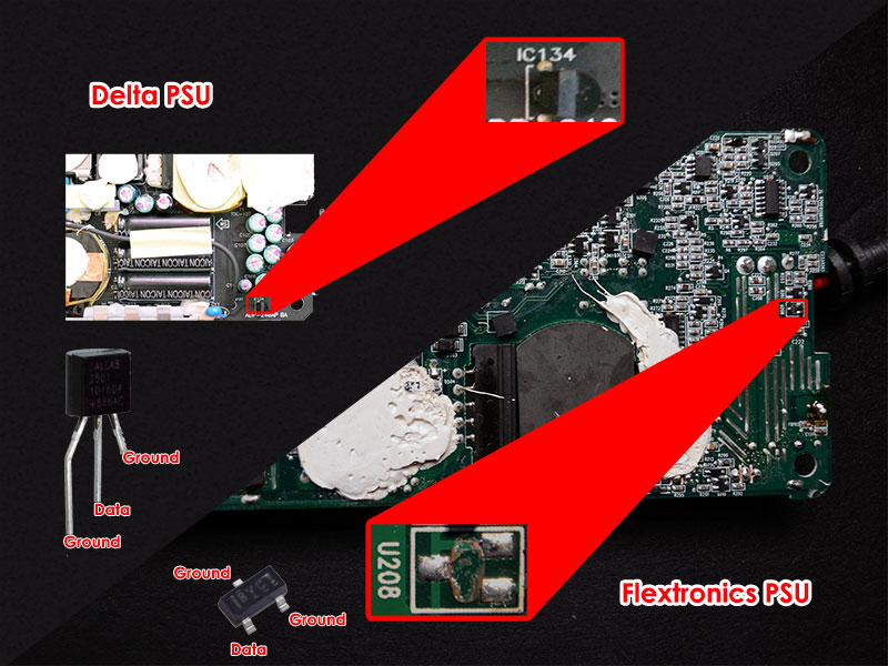
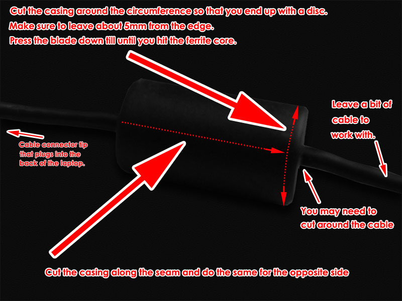
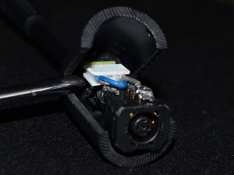
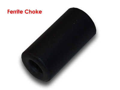
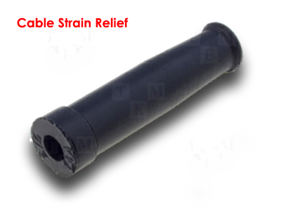
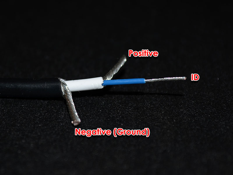
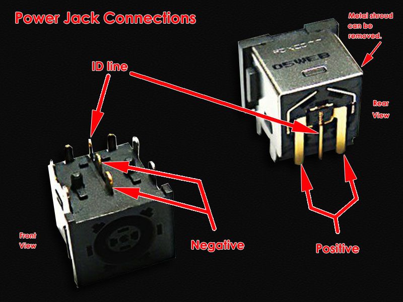
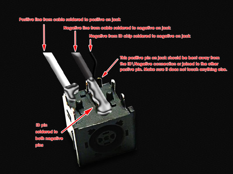
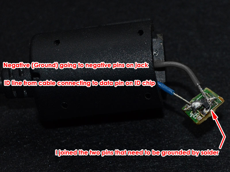
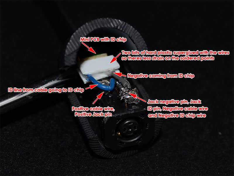
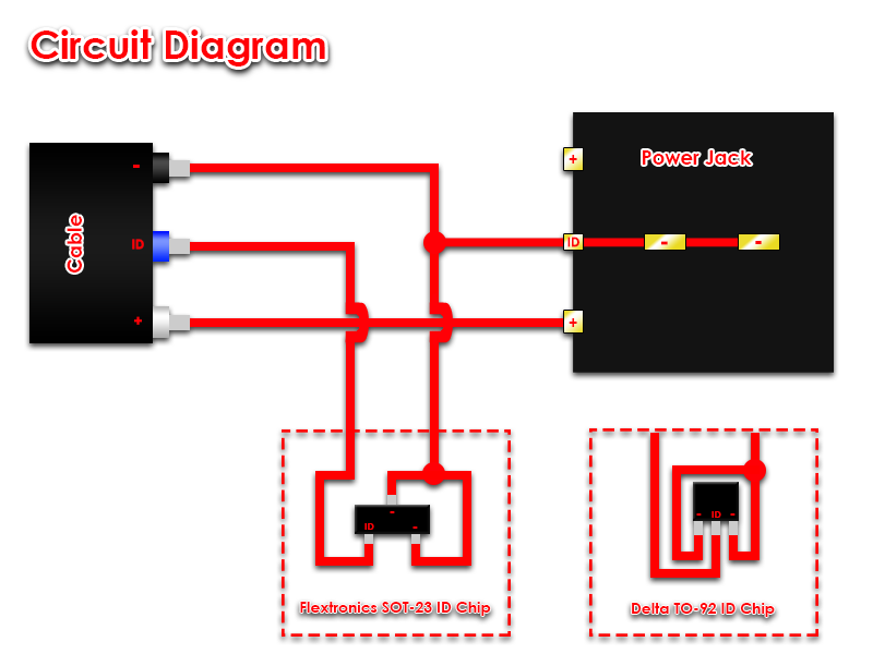
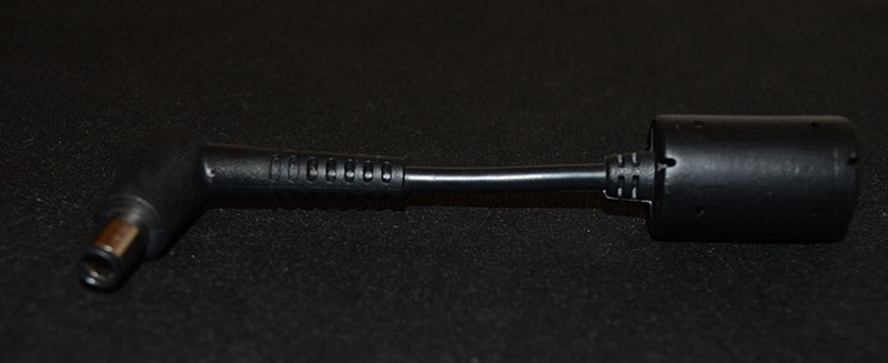
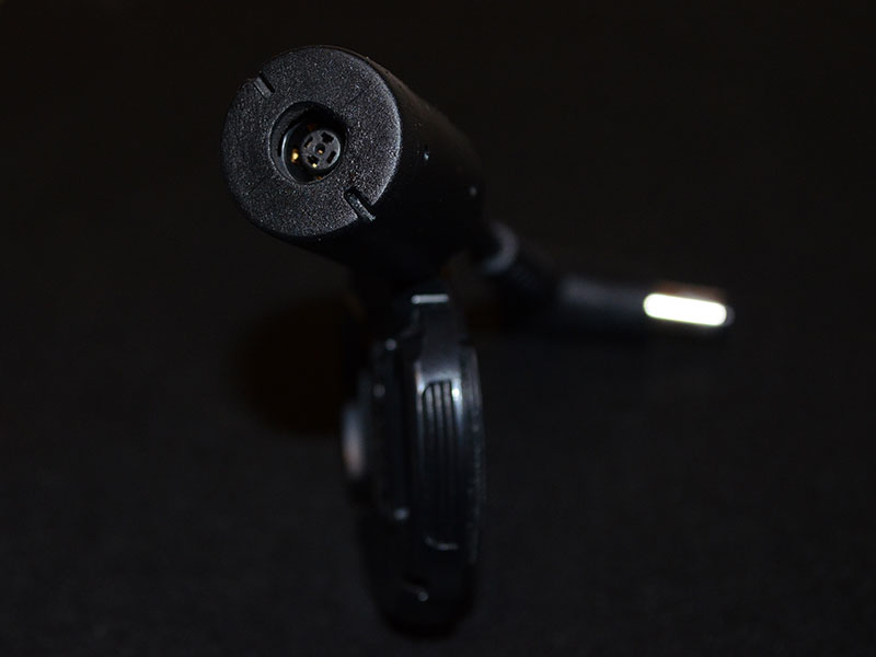
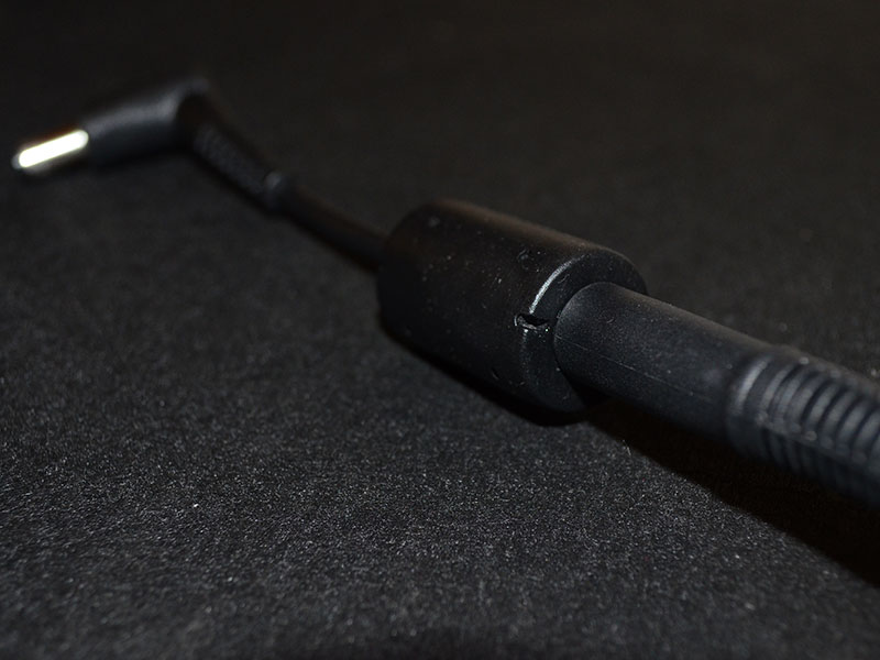
This modification involves going a step further than a straight ID chip swap between the 240W and the 330W. The reason I chose this method was, I did not want to perform the mod again in the rare case that the 330W died and I had to get a new one. In order to complete this mod, you will require the following items. 1. Dell 330W PSU (This PSU was built for the M18X and X51 product lines). Part Numbers: Y90RR / 5X3NX / F0K0N / XM3C3 / 331-2429 2. Dell 240W PSU (Either a Flextronix or Delta). Part numbers: PA-9E / J938H / Y044M / U896K / J211H / Y044M 3. Dell or HP standalone PSU cable/Connector. I used a right angle connector but any Dell/HP 7.4 x 5.0mm barrel connector will work. 4. M17x/M18X Power Jack. The part number for this power jack seems to be P01E. Look for the one that resembles the one used here. 5. Small PCB designed for a SOT-23 packaged chip. (If using the Flextronics 240W PSU). 6. Small housing (Optional depending on whether you would like to mod the ferrite choke housing) PSU DISASSEMBLY First we begin with the disassembly of the 240W PSU to retrieve the ID chip for our adapter. Since I had the Flextronics version some of these steps might not be the same for the Delta PSU. We start by lifting up the rubber feet on the bottom of the 240W using your nail or a flat tool. Underneath each rubber foot you will find a screw which you can go ahead and unscrew. One of the screws will be a tamper-resistant Torx T10 type, the difference to a normal Torx T10 being a small pin the centre so you would have to use a Torx screwdriver with a hole in the center. TIP: If you do not have this tamper-resistant screwdriver you can use a normal Torx T10 screwdriver but you will have to hammer down the pin at the centre of the screw slightly in order to get the normal T10 screwdriver to grip. Once you have removed all screws you will have to pry open the casing. I stuck a thin knife between the power plug and the casing to gently pry it open. The top half and bottom half of the casing are held together by interlocking clips. Twist the case a bit to get them to unclip. Then remove the PSU from the case. You will then be presented with the first metal layer which is held on by tape. Cut the tape and slide out the first metal layer. You will then see the second metal layer which is held in place by 3 points soldered onto the PSU PCB. It is indicated in the picture below. Desolder all 3 points and remove the second metal layer. The last layer is black and seems to be a type of flexible hard plastic. It will be stuck in place by white thermal stuff on the PCB, simply lift it and peel it away. Depending on whether you have a Flextronics or Delta PSU your ID chip will look different. Desolder this chip and keep it in a safe place (If you lose it, you have to buy a new 240W PSU). On the Flextronix PSU the chip is also stuck in place apart from being soldered on, so you have to work quickly heating the solder and pushing the chip away with a bit of force. To reassemble the PSU reverse the above steps. You can still use this PSU connected to the adapter with your M17X so it won't be collecting dust. THE ADAPTER MOD You will have to decide on whether you want to mod the ferrite choke housing into your enclosure or use a dedicated enclosure (small as possible as this circuit is tiny). If you are using a dedicated enclosure jump straight to the labelled wire photo to continue. If you would like to mod the ferrite choke housing continue reading. I did not take sufficient pictures during this portion as I was unsure if the ferrite choke housing would work. The rubber around the ferrite choke and the connector that I purchased was soft and very flexible which made it easy to work with. I used a knife and pressed against the rubber of the ferrite choke housing for a clean cut so that I could glue it back together. I cut off one end and then length ways along either seam of the housing making sure to leave a bit of extra cable. Here is a picture of what we’re trying to achieve with the cutting. You will then see the ferrite choke which you can crack with a hammer. Remove the pieces (be careful as they will be very sharp). Then the cut off the cable strain relief that's covering the cable with small wire snips. You will then see the cable which you can strip to positive, negative and the ID line. You will then need to connect those wires to the power jack. The two pins at the top are negative. The two pins at the back forming the shape of a U are positive and the pin at the back in the centre is the ID line. Solder the positive wire to positive pin and negative wire to negative pins as shown in the image below. The negative wire can be soldered to the negative pins and simultaneously joining the ID pin on the jack. The reason behind joining the ID pin to the negative pins on the jack is because we need to ground the ID line coming from the 330W in order for it to operate beyond its artificial 240W limit. Now all that’s left to do is connect the ID chip. If you have the Flextronics PSU the ID chip will be in a SOT-23 package and the Delta ID chip will be in a TO-92 package. The Flextronics SOT-23 package is difficult to work with and should be first soldered to a bit of PCB that had a SOT-23 package so that you do not break the legs off. I initially soldered the wires directly to the legs and moving it about in my "enclosure" to find the best spot to place it was too much stress on the chips tiny legs and they broke off... yes, all of them. Luckily I could still see a tiny bit of metal from each of the legs. I managed to salvage it by soldering it to a piece of PCB that I jacked from a broken mouse which had SOT-23 connections. The blue ID wire coming from the cable needs to be soldered to the data leg of the ID chip. Connect the remaining two pins from the ID Chip together and then to the negative connection on the PSU jack. Dont judge my pathetic soldering skills! Place your ID chip into the enclosure and test the adapter to make sure all your connections have proper contact. If it’s working properly you can close it up. I considered flooding the enclosure with silicone to secure the ID chip and its connections but I did not, as I thought it would be more work if one of the connections broke and I had to open it up again. You can do it if you like. I used a drill to make the hole at the centre of the disc large enough for the 330W connector tip fit through. I then stuck the enclosure back together using superglue along the sides and then attaching the disc. Add a bit of glue to the disc/jack so that the disc and jack are stuck together as well. This is so that the jack does not move when plugging the PSU connector tip in. THE COMPLETED MOD Pros/Cons over the ID Chip swap Mod Pros - Allows you to use any PSU irrespective of wattage as long as the connector tip is compatible with the power jack. - If the 330W PSU dies all you have to do is plug a new one in. No need to perform the mod on a new 330W. - No need to open up the 330W at all. - Your ID chip donor 240W PSU can still be used with your M17X by attaching this adapter. Cons - Allows you to use any PSU irrespective of wattage as long as the connector tip is compatible with the power jack (Could be dangerous with low wattage PSU's). - A lot more work compared to swapping the chips. Notes: I also had to trim a bit of rubber at the right angle connector for the cable I used as it’s a bit of a tight fit if you don't. The rubber around the connector did get a warm at the right angle after testing but it's being blasted by the heat of the CPU fan continuously so I don't think it’s the connector itself that's causing it. These cables are very short and should be able to handle the power easily. Since there are two positive terminals you will have to either split the positive wire coming from the PSU connector to each pin or join both pins (bend one pin over to the other and solder them together making sure to place an insulator to cover the ID pin) and solder the positive wire to a single point. Also worth noting is that this adapter mimics the original 240W adapter perfectly. So if you experienced the "plugged in, not charging" issue when connected this adapter will not resolve it (I still have to pop the battery and clip it back in to resolve). Credits: @imsolidstate, without his in-depth investigation this would have not been possible. His website detailing his investigation and the ID chip transplant can be found here and the subsequent update here. DISCLAIMER: Perform this modification at your own risk. I take no responsibility for any damage caused by technical error, user inexperience or stupidity.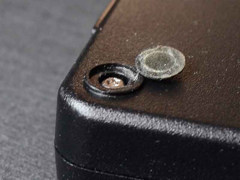
- 69 replies
-
- 15
-

-
Great news about the card @AssimilatorX Pity about the vBIOS incompatibility though. Did you try the ES vBIOS I posted earlier? It's a 015.013 version running 750/1100 clocks but that can be changed easily if the card works with it.
-
M17x (All revisions) OSD Icons by Nospheratu
Nospheratu replied to Nospheratu's topic in Alienware M17x / AW 17
@J95, I don't think its the OSD exe throwing that error. I've done some googling and and it seems its a Windows security feature to reject modified exe files. If the file is modded the signage is broken. Appparently this has been going on from Vista. There must be some setting that's still allowing Windows to validate the exe before running it on your system. Have a look at this link. edit: Even though UAC may be disabled the setting that I mentioned above may still be enabled. -
I'm not quite certain. My guess would be the card is DOA or that the DELL vBIOS is somehow causing your symptoms. I'm unfamiliar with CLEVO systems and not quite sure if there are beeps or signals that you should look out for. I suggest starting a new thread as you will get more appropriate help.
-
M17x (All revisions) OSD Icons by Nospheratu
Nospheratu replied to Nospheratu's topic in Alienware M17x / AW 17
Thanks for the thorough testing and feedback @J95. Could you please try the steps below and see if it resolves the problem. - Run gpedit.msc from the start menu. - Go to Computer Configuration/Windows Settings/Security Settings/Local Policies/Security Options. - Change the value of User Account Control: Only elevate executables that are signed and validated from Enabled to Disabled. -
M17x (All revisions) OSD Icons by Nospheratu
Nospheratu replied to Nospheratu's topic in Alienware M17x / AW 17
Sorry J95, I mistook your current version with the Windows 7 version. I only have the Windows 8 version modded there. I will try to mod the Windows 8.1 version and upload it for you. edit: @J95 I have added the Windows 8.1 version to the first post. Please test it and let me know if there are any problems. -
BIOS / VBIOS modification request thread (svl7)
Nospheratu replied to svl7's topic in General Notebook Discussions
OverDrive should work. If its not too much bother you could try re-installing your Catalysts to see if its detected. -
BIOS / VBIOS modification request thread (svl7)
Nospheratu replied to svl7's topic in General Notebook Discussions
Wow awesome score! Hmmm that's checksum is weird. I downloaded it again and checked using HxD which I use to mod and the checksum is still F400. I normally use ATIflash in DOS and it always reflects the same checksum value that HxD reports. Is OverDrive working correctly? -
M17x (All revisions) OSD Icons by Nospheratu
Nospheratu replied to Nospheratu's topic in Alienware M17x / AW 17
Did you download the "M17x R4 & M18X R2 (Windows 8).zip" version? Are you getting the same error when you restore your backed up original exe? I used the latest OSD for the R4 from Dell for Windows 8. The setup file is "Application_WD6DW_WN_v0.32.0.7_A02.EXE". edit: I just noticed that you mentioned the version you have installed is 0.32.0.8C. That version is for the Windows 7 install. The Windows 8 install is version 0.32.0.7 which I have modded. If you are running Windows 8 that is the version you should have installed before overwriting it with the modded exe. -
BIOS / VBIOS modification request thread (svl7)
Nospheratu replied to svl7's topic in General Notebook Discussions
I modded a P150EM 7970M vBIOS for another user here if you'd like to try it. It has 1100V version as well and checksum is in the post.- 477 replies
-
- 1
-
-
- bios mod
- bios mod request
- (and 3 more)
-
[M17x R2] with AMD 7970M CrossfireX
Nospheratu replied to StamatisX's topic in Alienware M17x / AW 17
Your 5870M x-brackets wont fit as the 7970M GPU die is bigger than the 5870M. Some users have modded the brackets by either chopping it up or filing the square portion bigger but I would advise against it. You rather get the proper x-bracket to avoid any damage/warping of your card. A 6970M/6990M/7970M x-bracket is the one to get. If you get a Dell x-bracket you can use the 5870M screws if its the CLEVO x-bracket you will have to get CLEVO screws. Be sure to check the rear of the card as sometimes the x-bracket is already stuck to the back, if that's the case you don't need to buy one. The 5870M heatsink needs no modification and is a perfect fit. There's only one PSU that's decently priced and has been documented to work and that's the M18X/x51 330W from Dell. Amazon is generally cheaper than ebay but I've noticed the prices have recently gone up. -
With a single 7970M you wont have to downclock or undervolt at all. Although at stock clocks you may want to undervolt as the card runs cooler. Fans don't work on auto for Dell 7970M cards in our machines although AlienHack was able to get his fans on auto, Display Port, HDMi video and audio working on his Dell card by using the vBIOS that came with his 7970M ES version. I've attached it if you want to give it a try. You're fortunate in that you're able to program the vBIOS chip directly if it ends up being incompatible. Disclaimer: This vBIOS file is intended for AssimilatorX as he is able to program his vBIOS chip if this vBIOS bricks his card. DO NOT DOWNLOAD AND FLASH this vBIOS if you are not prepared to deal with the consequences of it potentially bricking your card. Flash at your own risk. 7970M-ES-1000v.zip
-
That's brilliant news man Please let me know how it goes, I'm quite interested to see if there's a particular vBIOS that works with 015.022 cards on our machines. It might make it easier for R2 users to purchase 7970M's without worrying whether it'll work or not.
-
[M17x R2] with AMD 7970M CrossfireX
Nospheratu replied to StamatisX's topic in Alienware M17x / AW 17
It's no struggle at all. You can use your current CrossFire cable with the 7970M's and if you want to overclock you will need the modded 330W when you get the second card. The 7970M's are MUCH cooler. With an ambient of 32C here my idle temps are 38C and load temps are around 70C if I remember correctly. This is with the standard clocks of 850/1200 and 0.975v. My 5870M's used to idle in the +- 48C's and load used to reach +- 88C. -
[M17x R2] with AMD 7970M CrossfireX
Nospheratu replied to StamatisX's topic in Alienware M17x / AW 17
See my reply to your other post here. Are you saying the card is currently flashed with a bad vBIOS ie. its currently bricked? I don't mean to burst your bubble but that doesn't sound good especially since the original VBIOS is version 015.022. The M18x heatsink will not fit, its too large. -
The RGB LCD incompatibility is only applicable to CLEVO 7970M's. Dell 7970M's when used with our machines don't have this problem. From what I understand other vBIOS's for the CLEVO cards do not detect our RGB displays correctly and treat them as a 3D display which over time damages it. This is just a theory though, don't worry about it since you are safe with the Dell card. Use SVL7's vBIOS mod pack as most users are using it with the DELL cards. Is there any particular reason you want to use a modded vBIOS? The reason I ask is I see your vBIOS version is 015.022 and cards shipped with that version usually are incompatible with R2's and will not provide display after installation. Downflashing the card may also lead to bricking the card.
-
[M17x R2] with AMD 7970M CrossfireX
Nospheratu replied to StamatisX's topic in Alienware M17x / AW 17
Welcome to T|I nitsun69 Ask the seller to take a photo of the rear of the card and mail it to you. Normally there is a sticker at the back that indicates what vBIOS version the card was shipped with. This should make your decision easier. Depending on your needs I would recommend getting a CLEVO card instead of the Dell you have in your link. If you require working HDMi audio get the Dell but you will have to use HWinfo for fan control. CLEVO cards on the other hand have auto fan control which is more important to me personally.