AngieAndretti
-
Posts
50 -
Joined
-
Last visited
Content Type
Profiles
Forums
Downloads
Everything posted by AngieAndretti
-
Alienware M17x R3 upgrading to GTX 780m
AngieAndretti replied to cheetos82's topic in Alienware M17x / AW 17
So then it appears possible to put an nVidia GTX 780m into an Ivy Bridge laptop like the M17x R3. I was thinking at first that I'd seen somewhere that it wasn't going to be possible but that's awesome! I'd like to run that upgrade sometime in the future when I can afford the card - but I'll be sticking with Windows 7 on my M17x. J95, that instructional info is a great post, looks very helpful! Has anyone else gotten a 780m working in their M17x / M18x or similar machine? What's your performance increase like versus whatever original card you had? I have the AMD 7970m myself. Thanks. -
ALIENWARE m17x r4 7970m Switching issue
AngieAndretti replied to ZEQ2Mapper's topic in Alienware M17x / AW 17
13.3 beta 3 is the best Catalyst driver as of now. They have a 13.5 beta but it's NOT as good on my system, like way worse, and buggy! I'd advise an update to 13.3 and if you use svl7's modified BIOS (available here) you can configure your video options right in the BIOS at startup. You'll find a place under Advanced -> Video where you can switch from [sG] meaning switchable graphics to [PEG] which is your 7970 card. I must say though that I don't understand you pressing Fn+F7 and it disables everything. Are you saying that when you do that it reboots and there's no video output at all? What do you do to recover? -
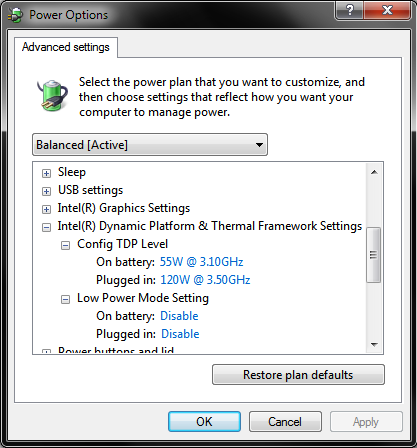
Note: Tried and Reverted. No differences seen in general system performance (since CPU microcode update does not apply to my system) BUT Intel DPTF does not seem to function correctly with A05 BIOS installed. It's still present in the BIOS but it no longer interacts correctly with the Windows environment. This would not affect users of unmodified M17x's but I have installed the DPTF driver from the M18x R2 and in combination with my 3920xm CPU and some configuring in BIOS, it allows me to set custom changeable TDP's and max non-turbo speeds as part of my Windows power profiles - and to drop the CPU into an ultra-low power state (800MHz) if desired. Tried re-installing DPTF driver after downgrading to A05 but this functionality, despite being configured identically in BIOS, was lost in Windows when running A05. You gotta admit this changeable TDP thing is pretty cool so I'm going back to A10 for now:
-
Hi all. I'm considering downgrading (blind-flash method, verified it works on this system before) my M17x R4's system BIOS from A10 Unlocked to A05 Unlocked. Reason being the idle clock for the Intel iGPU - I liked the behavior much better in A05 and earlier. I was able to idle at 350MHz(qm chip)/400MHz(xm chip) instead of the advertied 650MHz, which results in significant idle power savings. The new BIOS does still allow for this, but only if the system is exposed to AC power (yes, adapter is original.) The problem is if I have to restart my system for any reason while on battery power, I get stuck with 650MHz iGPU clock and a 25% greater overall idle power draw until I can plug in. I've documented this behavior further in a previous post, but for this question let's not focus on the reason I want to downgrade - unless you know another way I can force the behavior I want. What I want to ask is this: Other than the CPU microcode update which does not apply to my current ES CPU, the new Windows 8-related features, and the slightly faster POST, are we aware of any other meaningful differences between the two BIOSes? Differences in system performance? I did notice a slight improvement with A10 over A05 on my previous CPU but I attributed that to the microcode update, which no longer applies to my current CPU. I've yet to run A05 on my current ES CPU.
-
I'm running the Kingston HyperX 2133MHz in my M17x R4. Originally I had problems at boot as described in this thread, but I MOVED THE individual MODULES AROUND until I found a placement combination the system liked. Once I found that placement combination that worked, it's been 100% stable and very fast since! To anyone who has/wants to try this RAM: Try moving it around if it doesn't work at first. I know it sounds weird and we shouldn't have to do this BUT I've seen the same behavior with six different RAM modules and two different Alienware systems. Using Kingston's 2133MHz RAM, my system passes all RAM stress tests consistently and yields a 7.8 graphics score in Win7's Experience Index with AMD 7970m GPU, 3920xm CPU, Enduro Switchable Graphics enabled while using AMD's Catalyst 13.3 beta driver. My original factory configuration (1600MHz RAM, same GPU, 3740qm CPU, Enduro Enabled, Catalyst 8.934 driver) yielded a graphics score of only 6.9 - and was surprisingly lousy for gaming! That's the hidden benefit to these ultra-high-speed RAM modules: your integrated graphics uses system RAM so the faster your system RAM the faster your iGPU. For those of us who disable switchable graphics I guess it doesn't matter but personally I love my Enduro setup - now that I'm off the horrible drivers Dell provides, lol.
-
M17x CPU Fan Upgrade/Mod (2CFM->10.4CFM)
AngieAndretti replied to AngieAndretti's topic in Alienware M17x / AW 17
Yes that's a much better idea adding a heat pipe to the underside, assuming I can work out a path to route it. I'll have to open it up again n check that out. Thanks and good luck on your next mod(s) too! -
M17x CPU Fan Upgrade/Mod (2CFM->10.4CFM)
AngieAndretti replied to AngieAndretti's topic in Alienware M17x / AW 17
Khenglish, Thanks for the reply! Yes the new fan is slightly louder than the original, and the different blade design yields a higher pitch sound, but it has not been bothersome. I would not call it *significantly* louder. The new fan sounds about the same as it does in my M14x R2. For all tests before and after, I allowed the system to auto-control the fan. I've played with using HwInfo64 to force the fans to run full blast but the program cannot seem to control the CPU/GPU fans SEPARATELY on my system so I haven't done much with that. My CPU's realtime power draw reading hangs around 64-67 watts while stress testing at 4.1GHz. If it does get too hot and the speed drops to 3.5-3.7GHz, the draw also drops to 52-55 watts for the same duration. I'm not sure if it could operate at 4.1GHz under full load while drawing less than ~65 watts. My current clock multipliers are 44x1 core, 43x2, 42x3, and 41x4 cores. I established those settings to keep the temps down before doing this mod (a higher clock is no good if it throttles down during gameplay, etc.) so I honestly don't know how high I could go with this CPU now. I've seen screenshots indicating it can do 4.6GHz on all four cores in an M18x unit but I notice that it wasn't actually under any load in the screenshot so I'm not sure about that. So you're the one with the four-pipe cooling mod right? I've mused with the idea of adding a third pipe to my setup, like soldered it on top of the existing two pipes, but I'm not sure how much that would help or what's involved as far as heat tolerances for the overall heatsink assembly. I don't want to mess up the radiator fins section by getting it too hot during soldering. -
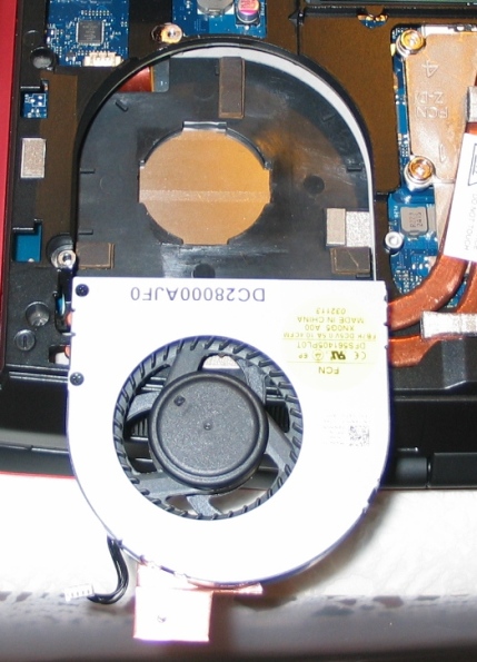
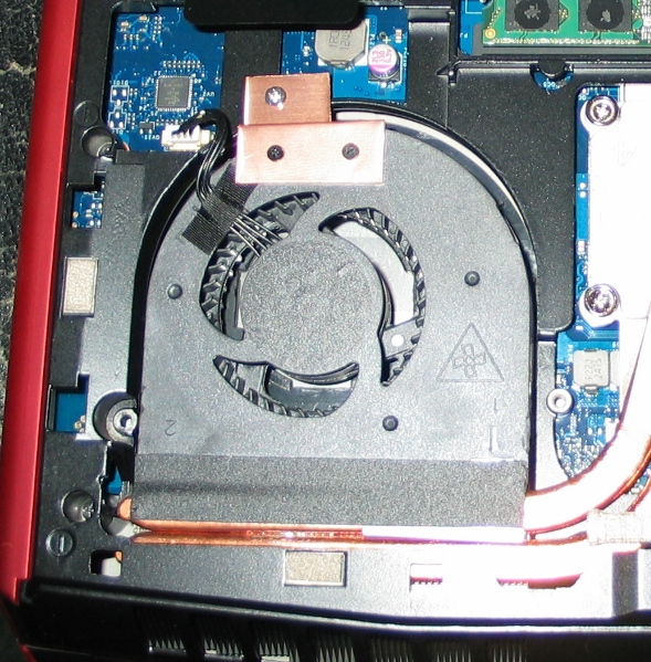
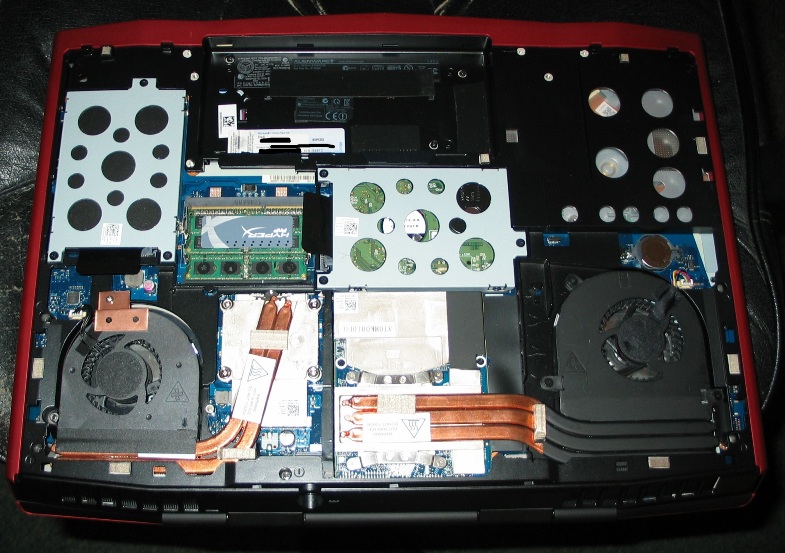
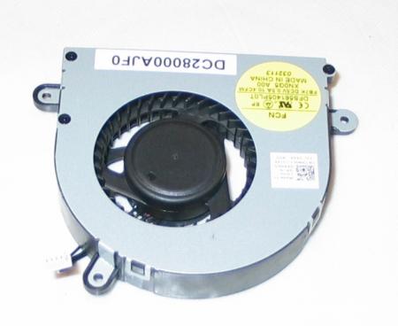
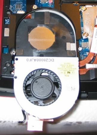
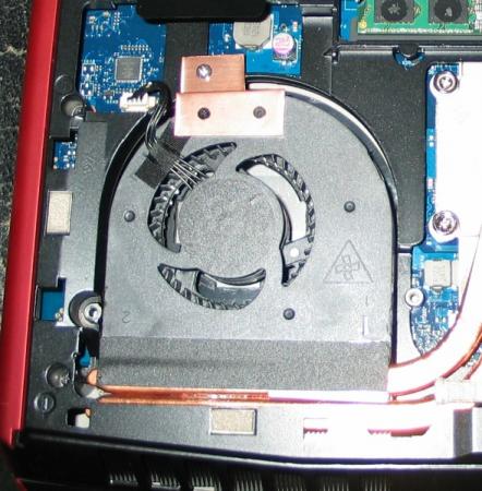
CPU Fan Upgrade Procedure for M17x R3/R4 (2.0CFM->10.4CFM!)<o:p></o:p> My original CPU fan was adequate (not great but adequate) fora 3740qm CPU @ 3.7GHz but when I upgraded to a 3920xm CPU and overclocked to4.1GHz x 4 cores, I needed more cooling - a lot more. Running a 60-second CPU stress test on all four cores in Intel XTU, with a 65watt CPU TDP programmed, and a core voltage of 1.351v, the difference is asfollows: · With original fan, system runs @ 4.1GHz for ~28 seconds before dropping to3.5-3.7GHz because of heat. On longerstress tests, it DOES NOT recover from this reduced speed state becausecooling is not adequate. Core Max: 92-95Celsius. · With this fan mod, system runs @ 4.1GHz for ~55 seconds before dropping to 3.7GHzbecause of heat. On longer stress tests,it DOES recover from this reducedspeed state and spikes of ~4GHz are seen for the remaining duration of thetest. Core Max: 92 Celsius every time. <o:p> </o:p> So here are the stepswith some pictures: 1. Procure an M14x R2 fan. It MUST be an R2 fan!! The fan blade design is clearly different so usemy picture as a reference. There are many eBay sellers, for example, selling the R1 fan as an "M14x series fan," implying that bothrevisions use the same fan - which is not true. The R1's fan has a 2CFM sticker rating while the R2's has 10.4! The markings to search for are: XN0G5 and/or DC28000AJF0. I got mine here: http://www.aliexpress.com/store/product/Cooling-Fan-for-Dell-Alienware-M14x-XN0G5/207462_647373968.html Note: Do not just swap the M14x's fan blade into your existing M17x fanshroud. I tried that first and it doesnot increase airflow. You need the newblade AND the new shroud for this to be effective. 2. Remove your original CPU fan. There are three screws that hold it in. Also disconnect its power jack from themotherboard. While you have access, youmight want to blast that exposed exhaust port with some compressed air to makesure everything is clean. 3. Notice the three mounting brackets that protrudefrom the sides of the fan shroud in the picture from Step 1. You'll need to cut them off so the shroudwill fit. I used a Dremel with agrinding wheel. There's also one smallblack screw in the corner with the yellow sticker. You'll need to remove it and grind down thatprotrusion as well. Save that screw forlater btw. 4. Make spacers/pads to hold the new fan up. The factory pieces will not line up so you'llwant something under the fan for clearance and to allow air intake from theunderside. I used small pieces of arubber material called Dynamat but padded mirror tape would work, as would manylayers of electrical tape placed on top of each other. It doesn't matter what you use - as long asit won't melt - and you'll want it to have a small footprint so it doesn'tblock airflow. I made my pads abouttwice the height of the factory material. Higher pads will allow for greater clearance and more air intake - justbe sure the fan still lines up with the heatsink and the case closes over it. This picture shows the three pads I made, and the fan shroud with its originalmounts ground off. 5. Create a mounting bracket to secure the fanshroud at the point farthest from the exhaust port. You could optionally fabricate mounts to lineup to all three screw threads on the case, but with my sturdy rubber pads andthe tape that will be included on the exhaust side if you buy your fan new, Iwas fine with only one new mount. Note: Leavethat tape covered until the end of Step 7. I used a thin piece of copper but any metal is fine. Bend the metal so it lines up to both the topof the fan shroud and the point above the screw thread on the case. Mark how it sits on the fan shroud and drill twotiny holes (1/16" bit) through the shroud-side of the mount. Now place the mount on the shroud using yourmarkings and VERY CAREFULLY drill further so that you have holes going throughthe plastic as well. Do not push hardand do not hit the fan blade within! Drill a slightly larger hole on the case-side of your mount where itwill line up with the screw thread. Thescrew you saved from Step #3 can be used for one of the shroud-side holes andwill not hit the fan blade within. Ifyou can come up with another similar screw, use it for the second hole. If not, you can take one of the other twofrom the shroud assembly if you want. It's also held together with clips so it won't fall apart. One of the three screws that held in youroriginal fan shroud can be used for the other (case side) of the mount. 6. Thoroughly blow off your new shroud inside andout with compressed air to remove any stray plastic scraps from the machiningprocess. 7. Fit everything up, making sure the fan sitsflush on all the pads you've made. Makesure it lines up with the heatsink and isn't too high or too low into thecase. Adjust pads as necessary. Once you're satisfied, screw in your mount tohold the fan in place. Now lift up thetape on the exhaust side (which should still be covered) and remove thecovering. Carefully fold the sticky partdown onto the copper heatsink pipes to secure that side of the assembly. 8. Plug in the fan's power jack. Again, ignore the connector being a differentcolor. It fits and it works withoutmodification or programming. 9. Close your unit up and enjoy!! So there it is! Let me know how this works out for you guys if you try it - and what you think about the procedure itself. Suggestions/questions are always welcome! * I obviously assume no liability if you break anything doing this. Informational purposes only, etc, etc, * This procedure replaces the M17x's original CPU fan (and fanshroud) with that of the M14x R2, and yields a greatly increased fanoutput. Both fans use the samemotherboard connector (ignore the color difference of the jack) so all that'sneeded here is to procure an M14x R2 fan, modify the mounting system a bit soit fits, and connect it up - and it works like a charm!

-
The 10.3CFM rating is actually on a yellow factory sticker on the fan shroud itself. That's what I'm going by. There's a similar 2CFM sticker on my M17x CPU fan. I'll admit that great a difference seems hard to believe but those are the ratings on the actual hardware. I can attest that the M14x fan does truly push more air than the M17x's because I ran both outside the respective laptops for comparison purpose and while outside the laptops the exhaust port size is the same on both fans, but it was still clear by my own observation that the airflow was greater with the 14's fan.
-
Temisan - installing the new XM cpu was very easy in this system. Everything you need to access is easily accessible in the M17x. The only aftermarket/extra thing I used was high-end heatsink paste. Regarding the fan swap, the M17x mobo CAN control the M14x's fan. That much has been verified. The issue with the first attempt was the difference in fan shrouds between the M17x and M14x. Simply put, the 14's fan shroud will fit into the 17 but it is shorter from exhaust-end to opposite end and none of the screw holes line up. My second attempt will be to adapt for these issues using the 14's original shroud in the 17 because the first attempt tried to free the 14's fan from its shroud and "transplant" it into the 17's shroud. That was an epic fail. The fan lives in its shroud and cannot be removed from one and put back into another without damage - so I have a replacement M14x fan on the way for my next try. Also the top and bottom circular air-intake holes in the 14's shroud are slightly larger than the 17's, which means it will be better to use that shroud anyway. I'll just have to fabricate an adapter to hold it in place. I will post pics n stuff when I get it working!
-
This is a weird quirk that has stumped me for a long time and I've found nothing through my own extensive research (thanks Intel for your "confidential" PDF collection!) System is M17x R4 running A10 BIOS; Similar behavior seen on M14x R2. Installing RAM faster than original 1600MHz (verified w/ Crucial 1866MHz and Kingston 2133MHz) causes the base speed of the iGPU to idle below the advertised 650MHz. On 3740qm CPU it ran at 350MHz and with 3920xm it runs at 400MHz. It still ramps up as high as 1300MHz as needed for performance but uses a hell of a lot less power at idle - so I really want this behavior! With these power savings, I'm able to run my M17x on battery for nearly 6 hours! Really! Everything works great if I boot on AC power, even if I then switch to battery, even sleep/hibernate. The issue is that if the system is booted from a cold start or rebooted while on battery, the iGPU does its advertised 650MHz (which I do not want) and draws 2+ watts of power from the battery, even to do nothing. It stays like that until the AC adapter is plugged in, at which time it immediately switches down to 400MHz (verified w/ 2 separate 240w adapters.) With the desired behavior - running at 400MHz - iGPU only draws ~0.1 watts at idle doing nothing. It might sound silly but I really want those two watts of power savings ALL THE TIME, which I lose if I'm running on battery and I have to reboot for whatever reason. Can anyone explain this behavior? Has anyone else experienced it? It's not a huge issue but it has perplexed me for so long and I cannot find anything on the topic. I do know that downgrading back to A05 BIOS made my original 3740qm's iGPU run at the lower speed all the time, even when booted on battery, so I'm assuming that would work with this CPU too but I'd like to actually understand what's going on here - and if there's another way to control it. I'd like to be able to force it manually. I have tried lowering the iGPU clock multiplier in both Intel XTU and in BIOS (via the GT overclocking section) but it gets ignored.
-
No sry guys I made a mistake: just looked at my original vbios file and it's version 022 not 021 so I've gone between 022 and 017, never 021.
-
I've yet to try the 022 version of the BIOS, but I can say that I was able to go back to 017 after 021. Edit: My orginal vbios was version 022 not 021. Sry.
-
Hmm that's interesting - the claim that vbios version 017 uses a different stock 3D voltage from 021. Is that really true?? I've run both on my Dell card and monitored with HwInfo64, and I see 1.00v for my 3D clock with both, even though the vbios patcher tool lists the 3D voltage in my 017 vbios ROM file as 1.05v. I've also run the 1.1v and 1.075v modified versions of the 017 vbios by svl7 and in those cases HwInfo64 does pick up the stated 3D voltages as they're advertised. Weird. And as for the question of whether it's possible to downgrade the vbios, I started with 021 and can downgrade to 017 and back without issue.
-
Update: I'm passing my stress tests with the new settings, and so far no WHEA CPU parity errors either! Due to the extra voltage, my CPU is throttling down after ~30 seconds at full load test, compared to ~40 seconds prior, but if it's more stable I'll take it! My next project is going to be a cooling upgrade for this beast. I'm looking into swapping my CPU fan for something with a higher air output than 2.3CFM. I've noticed something interesting - the M14x R2's fan is in a shroud of identical size and shape, with identical wiring appearance, but the blade design is different and it pushes a lot more air! Even limited by the M14x's slimmer exhaust port I can feel there's clearly more air coming out when I manually set both to maximum fan speed. I stumbled across a page somewhere yesterday that claimed the M14x R2's fan is rated at 10.4CFM!! OMG right? The only trouble is I really don't want to cannibalize my secondary laptop for this project and spares of its fan look difficult to come by. Everyone is selling the R1's fan which is only a pitiful 2CFM unit with a blade design like what I'm trying to replace in the M17x. I'll post more on that later but any ideas/suggestions are appreciated in the meantime! Anyone out there already upgrade their M17x's CPU cooling system? I know the voltage/current requirements are the same for both fans in question (M17x CPU fan and M14x R2 fan) and the connectors look the same, as do the fan shrouds save one mounting screw position, but I wonder how the M17x's mobo will react to this different fan being attached. Like how universal is the speed control/sensor mechanism? I know the 14's fan has a higher top speed for instance.
-
Update: (and possibly the solution to my own question) I went back an further analyzed the screenshots I'd seen for the 3920xm and took notice of the 120w turbo power limits being used. Now My BIOS implies a long-duration power limit of 85w when you select Level 3 overclocking - and it doesn't allow the user to manually enter anything greater than 80w - so I kind of assumed that was as high as I'd ever be able to go on that setting but I was able to raise both the short and long turbo power limits in Intel XTU to 120w, matching what I see in the screenshot I'm working from. I also matched his additional turbo voltage setting of 195mv (which was previously ignored) and I'm seeing slightly higher voltages in HwInfo64. My multipliers are still the same as before but I'm seeing a max. of 1.351v up from 1.331v on the 85w turbo power limit. I also copied his setting of 1300 for primary plane current limit in BIOS. Changing that setting in XTU results in a very low number being shown in BIOS upon restart - something silly like 165 - and if I remember it may have crashed when I originally tried to apply it that way, so I believe that limit has to be modified in BIOS to be done correctly on this machine. He also limited his secondary plane (iGPU) limit to 128 in BIOS but I don't want mine that low (fullscreen flash videos run slow) so I'm starting with 256 which equals 32 amps for the iGPU. I'm not sure if that limitation will help me get more out of my IA cores (or whether I was ever really maxing out the iGPU at its default 50a limit) but we'll see how it goes from here... [Giving credit where it's due, the screenshots I'm working off of are done by Mr. Fox over at Laptop Forums and Notebook Computer Discussion and are available near the bottom of this page: M18x R1/R2 Sandy Bridge and Ivy Bridge CPU Overclocking Thread - Page 159
-
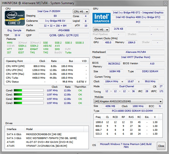
As I recently shared, I've upgraded my m17x R4 with a 3920xm ES CPU I bought on eBay - and I've been tweaking it a lot in the past days. I have my multipliers set at 44x1, 43x2, 42x3, and 41x4 cores. This appears to be as high as I can go without significant instability. The current settings ARE stable as long as the notebook is on a good hard surface (I also added bigger feet to the back to aid in air intake) but I'm noticing WHEA error 19's in my event log. These are processor parity check errors, basically saying it went back and checked its work and found that it got a different result the second time, forcing it to redo the calculation. This signifies that I'm on the edge of instability, and a google search indicated that the usual solution was to bump the CPU voltage up a *tiny* bit - However it appears that I cannot exceed my current 1.331v max (via HwInfo64 monitoring.) I can set the value higher in Intel Extreme Tuning platform and it appears to take the value (it even shows the increase in BIOS upon reboot) but going higher than +105mv (corresponds to 27 "additional turbo voltage" in BIOS) stops yielding higher max voltages in HwInfo64 - and appears to have no effect on CPU stability. When I look at Intel XTU / ThrottleStop screenshots of this same CPU being used in m18x's, I see vcore voltages of ~1.5v being achieved - enabling notably higher multipliers, but after lots of tinkering I'm unable to exceed 1.331v on my system. Is this a hardware limit of the M17x R4's mobo? A firmware/BIOS limit? Any suggestions for bypassing it? Other posts indicate that if I could even ramp up my voltage by something like +.05v, that could be enough to stop the parity check warnings without requiring me to reduce my speed - and I'll admit I'd sure love to see the 46x4 multi's that are being achieved at 1.5v... someday... with an overclocker's warranty from Intel.
-
My concern was that the BIOS flash might fail to recognize my CPU as being the ES stepping (i.e. different from expected/retail) and therefore it might try to update the microcode to something that isn't compatible with my CPU. I realize that sounds unlikely but since I'm not familiar with the particulars of updating CPU microcode in general, I decided it's better to ask and be sure.
-
That's great info! Thanks! And yes my CPU is an ES with stepping E0, so Microcode 10 is the newest applicable revision if I'm reading you correctly. Now that brings another question - what would happen if I had to for some reason re-flash my A10 BIOS in the future? A10 usually updates to microcode 15, but that doesn't apply to this CPU so would the process just skip that step, leaving microcode 10 intact? I'm trying to verify that if I did re-flash for whatever reason, it would not break anything. Thanks again!
-
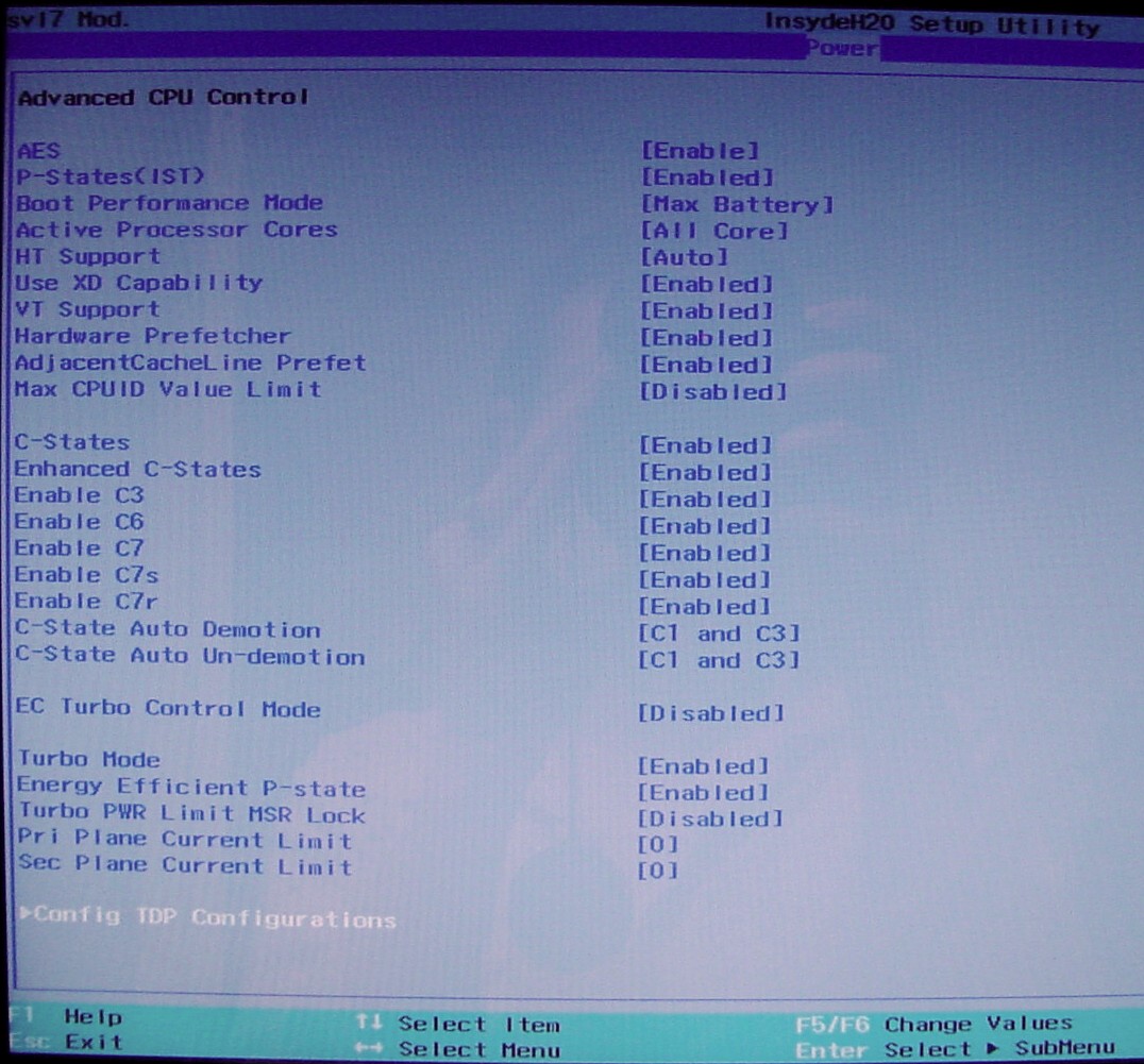
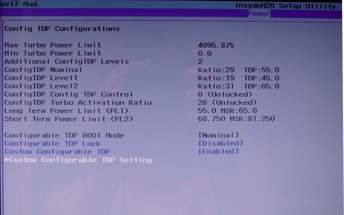
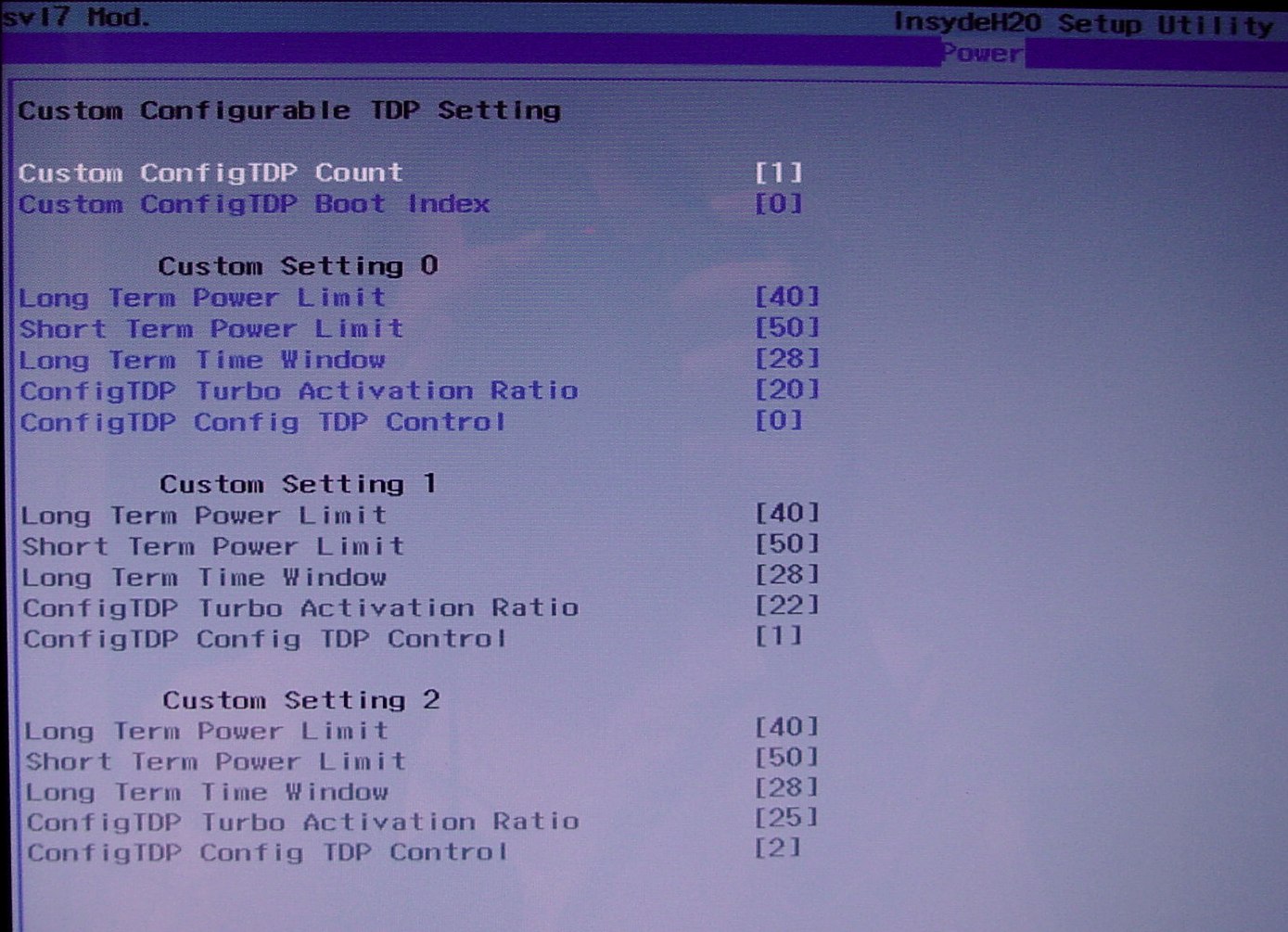
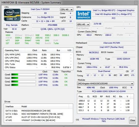
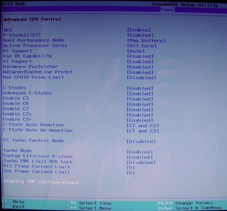
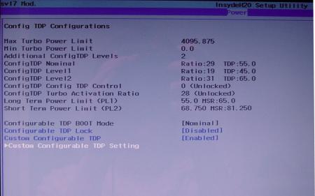
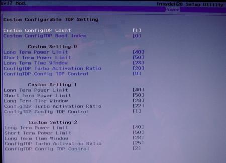
Hello all. I just received a 3920xm CPU for use in my M17x R4. After a bit of standard tinkering it is working great! With the addition of this new CPU, I have some new options visible in my modded A10 BIOS by svl7. The Advanced CPU Control window now shows "Config TDP Configurations" at the bottom. I will post some screenshots of these new options, which I have to do anything with. Here's my question: HwInfo64 shows my new CPU's microcode revision number as 10. I'm used to seeing 15 there, as revision 15 is included with the A10 version of the system BIOS. I'd like to load microcode revision 15 onto this new CPU by repeating my original procedure for loading A10 modded BIOS - but I'm not sure if the XM CPU's have a different version of the microcode. If I attempt to update the 3920xm's microcode with the copy included in the A10 BIOS, will that cause problems? Will I perhaps lose any XM functionality of this CPU? Sorry if that's a dumb question but this is my first XM CPU!!
-
[M17x R4] - 'unlocked' BIOS versions
AngieAndretti replied to svl7's topic in Alienware M17x / AW 17
All the DOS system files? Yeah, I have them all in the root of the drive; no folders anywhere. I think there may have been a CDROM folder with drivers in it but if so it came structured that way. I made everything as simple as possible to avoid possible compatibility/path issues. I know the drive works for other things cuz I've been using it as my 7970m BIOS update-by-DOS drive. I just added the necessary files (FPT DOS files and the A11 BIOS package files) to it for this new task of attempting BIOS update. Still I get the feeling we think it's DOS's fault, not the particulars of my laptop or a glitch in the update software, so I'll rebuild my thumbdrive from scratch tomorrow and see if I get anywhere... Is Nofew referring to the theft tracking option in BIOS? Lojack? I never enabled mine but does this mean I've altered that capability permanently by running the PRR tool? -
[M17x R4] - 'unlocked' BIOS versions
AngieAndretti replied to svl7's topic in Alienware M17x / AW 17
Okay I need some clarification please. I'm also getting: [PMODE/W] Abort: 00 Exception: 0E Error Code: 00000000 on attempt to flash (and even when just running the backup.bat) I did run PRR and I've gone over all the instructions carefully so I don't believe I'm missing anything. DOS version on my USB stick is Win98 DOS v.4.1.1998. Lighthalzen, I don't understand your post where you said you figured it out - "I also copied all the files from the folder..." I have everything where it should be on my stick. What exactly did you do to fix on your end? Thank you! -Angie. -
2133MHz RAM POST Issue (M17x R4, AMD 7970m GPU)
AngieAndretti replied to AngieAndretti's topic in Alienware M17x / AW 17
Thanks for the reply! I have tried reloading the defaults within BIOS but it does not solve the problem. Also I've verified that the behavior is present in stock BIOS A05, A10, and svl7's modified A10. Good news is that so far (probably jinxing myself as we speak) it's been more stable with two of the four installed ram sticks being the two new ones I recently purchased. The odd thing is that the arrangement of the sticks has made a difference from day one - and is still the case! All configurations do work once it's POSTed successfully that first time and all sticks test out as defect-free but it still makes a difference WHERE (in which slots) I place the individual sticks. Also oddly enough the pairs that were purchased together as kits do not like to be installed together. I have the new ones in slots 1 and 3 and two old ones in 2 and 4 - and that's how it wants to work! Placing the two new ones together in 1 and 2 I was unable to get a successful POST, even without any other sticks installed in 3 and 4. There was one stick in particular (one of the two I swapped out) that seemed to be decreasing POST stability so I'm going to cross my fingers and hope this configuration holds up as-is. I did experiment with a method for implementing manual on-the-fly graphics switching (similar to the behavior of the R3 units) which never needed a reboot to switch modes. This method increased battery life some while using the iGPU and I got full performance from my dGPU (taking Enduro out of the equation) but I found it confused some applications. Windows Magnifier and Flash-based content in particular crashed sometimes while in this mode. Also the Alienware OSD was unable to properly determine the center coordinates of the LCD screen - so it was not flawless but is likely deserving of further experimentation since Enduro just sucks in some games and this would be a nice workaround (for both my RAM issue AND Enduro.) Any other thoughts about the RAM and POST behavior are still welcome! Thank you. -
I've done this successfully with both my M17x R4 and M14x R2 (using respective original BIOS files of course.) The names to use on your flash drive for these laptops are M17R4.hdr and M14R2.hdr respectively. Also I've seen that you can leave the laptop's battery attached if you're feeling lazy and it still does work - just be sure to unplug the power supply cable before holding END and re-inserting cable. The part I've always wondered about is if you REALLY need to use an otherwise empty flash drive. I have three brand new Sony flash drives in use, one with just the M17R2.hdr file, a second with the M14R2.hdr file, and a 3rd with a DOS boot setup, ATIFlash, and some different BIOSes for my AMD 7970m graphics card. I'd be willing to bet I could combine all of this onto one drive, by adding the .hdr files to the ATIFlash drive, but haven't taken the risk and tried it yet.
-
Hello. I've been tinkering with this issue for a couple months now, and wondering if anyone can shed some light or help think of something I have not. Purchased new M17x R4 from Dell, roughly 3 months ago. Unit has i7 3740 CPU and AMD 7970m GPU. I Added 240GB Mushkin SSD for boot and slaved the original 750GB drive into the secondary bay for data. Upgraded original 1600MHz RAM to 16GB (4x4GB) of Kingston's HyperX 2133MHz DDR3. The 2133MHz RAM does run - and passes all stress/performance tests with flying colors but is generally "finicky" at POST. Laptop likes to come on for a few seconds and then shut back off until a successful POST happens after a few tires. Once it's worked once, it works fine from then on - until you change something related to hardware configuration/settings. I read the wiki page for modern BIOS POST process and I'm thinking this "working fine once it's worked" behavior could be due to BIOS building a "hardware table" that it can then just read from instead of enumerating and detecting everything from scratch - until something changes. I have verified to my own satisfaction that it's not defective RAM. I purchased some extra sticks and observed same behavior with only new sticks installed. Another note - the 2133MHz RAM will function without this issue if forced into 1866MHz mode in BIOS (but I don't want to do that unless I absolutely have to.) Now, for most purposes, it's fine to just leave everything as-is and once I've tried a few power-ups and gotten a successful POST (sometimes it even works the first time after tinkering) all is well. The one place it's an issue is with manual graphics switching. I have the AMD 7970m card with Enduro (which sucks for certain games unless Enduro is disabled.) I don't want to leave the laptop in exclusive dGPU mode all the time because I do use it on battery at times and the discrete mode cuts battery life nearly 50%... so I switch modes with the Fn+F7 and reboot method when I want to play certain games. This causes a full reset and the failing at POST behavior is observed when the unit tries to power back on (in discrete or switchable mode - it's the ACT of switching that's the issue.) Final note - I use svl7's modified A10 BIOS (have verified same behavior with stock BIOS versions A05 and A10) so I have a lot of available options I can tinker with. Here are the things I've found that INCREASE stability (lessen the chances of the failure at POST, or the number of times it will repeat:) Reduce power limits on the CPU in the Performance menu (this helps but even at lowest stock settings, does not quite alleviate 100%) In advanced CPU power options menu, change boot performance mode from "Max Performance" to "Max Battery." In advanced CPU power options menu, apply a current limit setting of 160 (20 amps) to 2nd plane current limit (integrated GPU.) The fact that these things make an impact suggests that available power at time of POST may be a component of the problem. I do own 2x 240w PSU's and same behavior is observed with both, as is on battery. I wonder if the issue could have to do with the 7970m card not supporting power gating? I have observed that if I hang out in BIOS for a while, the 7970 card gets extremely hot - so it's definitely sucking back the juice at boot time! Once I exit and Windows begins to load, the GPU fan will then spin up fast for a few seconds to cool the chip. It runs cool then-on unless under stress. Adding voltage to the RAM (1.55v vs. the standard 1.5v) DOES NOT help, and in fact decreases stability. If anyone has any thoughts or suggestions, I'd much appreciate! -Adieu, Angie.