jerryzago
-
Posts
24 -
Joined
-
Last visited
-
Days Won
1
jerryzago's Achievements
Settling In (2/7)
13
Reputation
-
I have the original dell and also bought another one for my dual sypply mod. I got the same one as you. Works great though either in dual psu mod or single.
-
So how it goes? The watt meter was causing all the trouble?
-
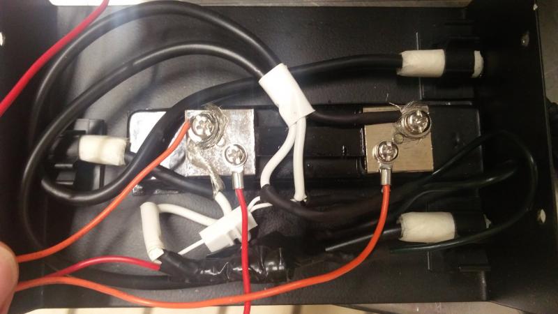
Diodes allow current in one direction only. + + D D Y + You connect one diode to each positive current of your psu, and the other end of the diodes together. You create a Y section. So current from both psus flow towards your laptop and not either way back. You could place on the negative side, but it is not needed. You can see the Y section in my pictures above, is is cover in black tape. Hope it is understandable.
-
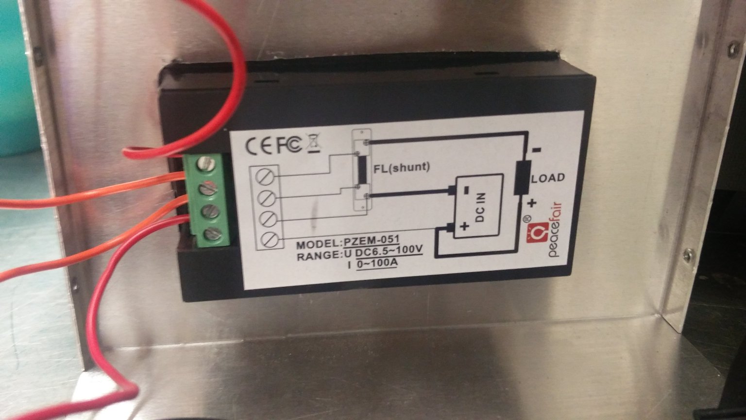
I live in Greece. I used once the Wemo smart wireless wattage meter. It showed me on a single Psu a maximum of 360watts. I don't have it anymore, since it was a part of a project and I had to give it. I could monitor wattage via app and store data. Anyhow, those things tend to show wrong values. Also keep in mind that if the device needs from the wall 360watts, and estimate an efficiency of 80% due to components and heat, then you have less that 300watts for your device. Just numbers.... If your bridge gets too hot, than also means a large amount of power is not getting to the laptop. Also in order to have the bridge operational, a small amount of voltage is reguired too. Diodes instead of bridges, don't heat up, and have a small Forward Voltage (voltage needed to operate). Psus due to their internal transformers keep some power stored, that is why you read voltage even though you have disconnected it from the mains. It is a normal situation so I don't think that this is the problem also. I installed this display to see what exactly is going on. It is wired after the diodes so it measures voltage, Amperage and wattage that the laptop receives, regardless the efficiency. I have read all your posts, and I also think it is weird to have this behavior. I told you that I had the same problems, until I removed the rectifier and placed diodes. Simpler and easier method. Also, no heat!!!
-
I have the original Dell and also this one. Part number is the same. Though cable is thinner (one cable for + and one for -) seems to be OK. Possibly a fake, or a newer model. I use two of them for my power mod, and both still play nice.
-
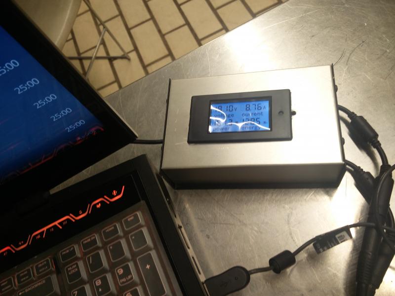
I am not sure what drivers I am using but all my games seems stable. Here is a picture with some load on the pc. During power ups, I see loads at 110max. How do you measure load?
-
Maybe, I am no so sure, because of high Amperage, your solder can get hot and not playing nice. Selecting a higher temperature solder (and possibly a higher wattage solder iron) will help. Make thicker connections and use shrink wrap to secure it. I wanted to avoid too many soldering for that reason. I saw that the signal cables were not soldered on mine, only screw tightened lol.
-
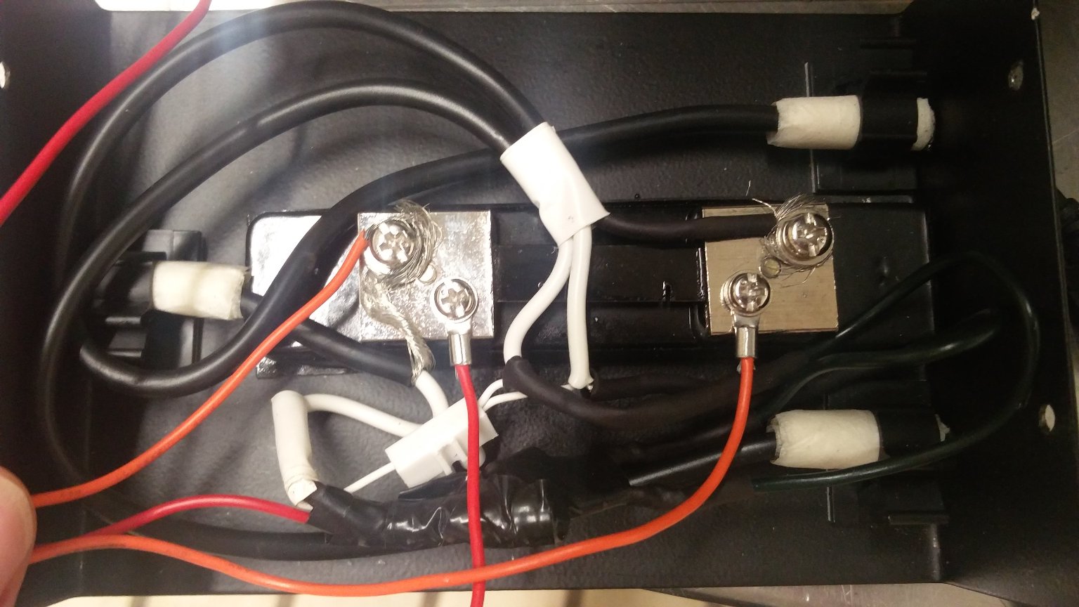
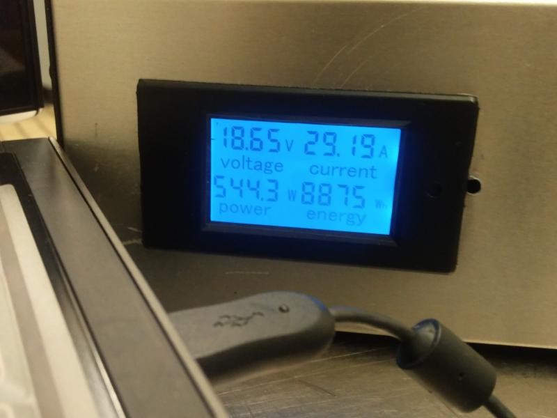
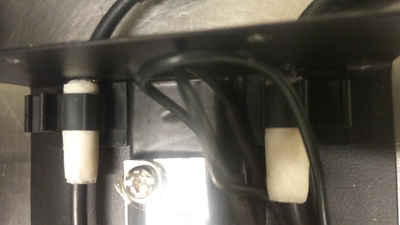
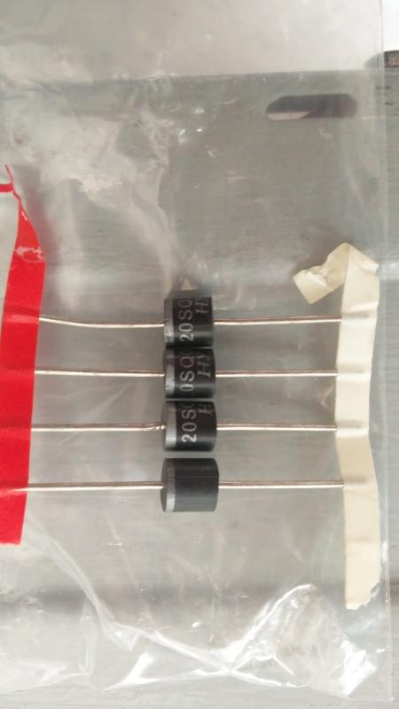
Here are some photos of my setup. I also have two psus. One is the official Dell with the other is a chineese clone. I also have the above part numbers and I am using only two. Take a look at the diodes I have used. I also never cut the original wires. I sourced some PSU extension cords and slice them for my needs. I am afraid to cut down PSU cables, because the amperage is too high. My diodes have a 20 amp tolerance and no forward voltage drop, so without powering up the laptop, I have a 19,44V and on extreme load (ex. benchmarking) I may drop to 18,64V. As you can see, the power delivered to the laptop is 544watss! My display is connected to the output area, so the numbers I am getting, are those reaching the laptop. Lastly, Please don't connect directly the PSUs together, You may have caused some damage. I can use a single one PSU, but I get throttling on high demand, despite doing the trick. Having two of them, the system is flawless. Keep in mind though, I don't have a 3920xm so my power draw is less.

-
https://el-supply.dk/mbr6050pt-schottky-diode-50v-60a2x30/varenummer/5-25MBR6050PT I suppose this one might do. I haven't taken any photos of mine. I can find my own diodes and sent a picture to you. I might have some to spare.
-
I would suggest not to solder them together without the bridge. You are reading lower wattage because current flows among the psus. I am starting to suspect, your bridge is not suitable for this job. Try using another one.
-
Nice setup there! My only concern is that blue and white are your positive current and brown is your negative current? I would suggest adding one more cable to each connector to your negative side, just in case. Two wires for positive current, two wires for negative current. After all, 20amps are quite a lot. I see you use a scotky diode. Measure output voltage (the one going to your laptop) when you stress your laptop. Measuring while only having the psu connected, isn't accurate. You mention seeing both lights from the PSUs come up? If both of them are connected to your mains, then it is OK. If you have connected one to your mains, and the other one is not, and it's light is on, the your rectifier is busted. Lastly, connect one PSU, put some load to your laptop (ex, YouTube video on FHD or 4K) and measure if the other side your rectifier has voltage. My thoughts for not working properly, are directed to your bridge. Perhaps a higher voltage/Amperage might help. I told you I used simple 20amp diodes used in photovoltaic systems. Positive cables have the diodes and then they are connected. I will try to post some photos if I have the time.
-
First of all, what model do you have? If you have the R2 have you installed the A11 unlocked bios, to help you switch between iGPU and dedicated GPU to elimate throttling? Process is in a link posted above. Lastly, do you use a bridge rectifier or high amp diodes? I used bridge rectifiers initially and the voltage reaching my laptop was around 18,3volts so under heavy load, the system shut down. I used two high amp diodes (20A) for the positive voltage cables (white in my occasion). Negative cables were soldered together (black ones). Also the psu signal ones (blue ones). Don't use anything else than solder. High amps don't like twisting or any other loose connection. I also have the original one and one I got from ebay. I haven't overclocked my CPU since it is a simple 3720qm. I placed my display AFTER the connections, so I have readings for the voltage getting to the laptop, Amperage and wattage. With the diodes, voltage drops to 19volts under heavy load, Amperage is around 34amps and wattage never exceeds 600watts. I am hoping to get a 3920xm someday and max out everything to see what the maximum power draw can be. I hope I helped you.
-
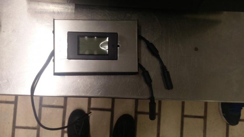
This post has been rather helpful. Thise who made the upgrade to dual 980m will need this. I finalize my dual psu. My design has only two 30amp diodes and modular design to connect one or two PSUs. I can add simply a third PSU anytime! I did use initialy a rectifier bridge, but the forward voltage was high, so the output voltage was too low (18,2 volts) so the laptop under full load, it tripped. My design also has a display and a shunt. It shows me output voltage, output amperage, total wattage and watts per hour. I can tell you that my 3720qm and the dual 989m with the dell vbios can pull 560watts during firestrike. I couldn't image what will happend when I have a 3920xm overclocked and premas vbios on the GPUs! My guess will be at 630+ watts. Everything is soldered inside and insulated. No heat is produced, but I put it in an alouminum box anyway.
-
You read my post on NBR? Yes. Everything you shutdown your system you need to do the gtx switch. To Save time, don't boot to windows.1) power system, 2) enter bios, 3) from advanced menu and video configuration select iGFX, 4) Save and exit, 5) IMMIDIATELLY enter bios again, 6) switch to PEG from the same menu, 7) Boot to windows, 8) Post results.
-
Throttling is back when you shutdown your machine. Upon boot make the GFX switch again and it is gone. Also throttling-fix isn't affected by making the system sleep.