Leaderboard


Popular Content
Showing content with the highest reputation on 07/16/14 in all areas
-
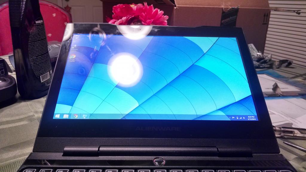
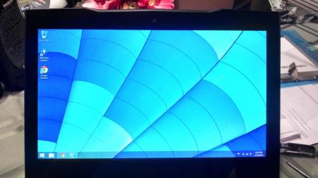
Hey, just wanted to post here, Me and another member of notebookreview.com have successfully swapped the M11X display panel with the LG LP116WH4(SL)(N2). I purchsed mine from laptopscreen.com and you will also need the lvds extension cable that they also sell. Its an ips display so it has awesome viewing angles, the colors are a little better and the blacks are quite a bit better. Its also quite a bit brighter. Brightness works just fine on the R3, and probably on the R2 (not guaranteed) due to the intel graphics being in control of brightness all the time. On the R1 Brightness control apparently only works when the intel gpu is active. I am not responsible for anyone who damages a laptop trying this.

 1 point
 -
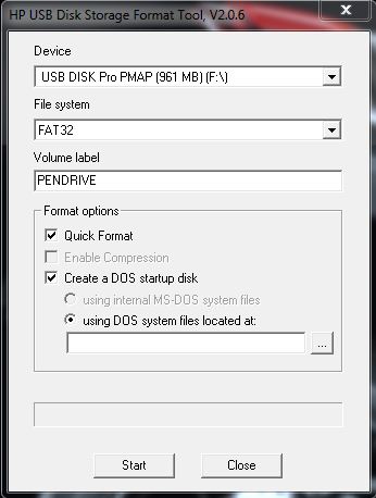
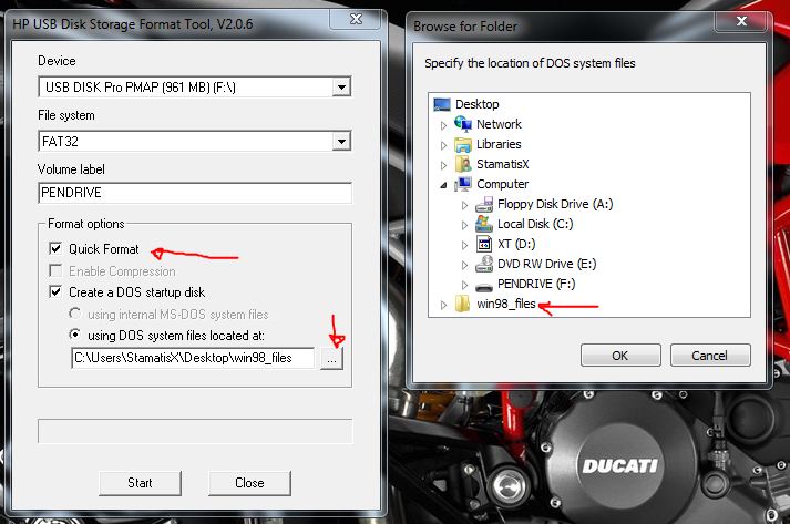
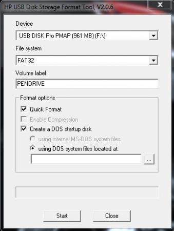
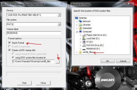
- work in progress - Instructions for flashing the VBIOS of an AMD / ATI video card: You'll need: A VBIOS file you want to flash The latest version of ATIflash, a DOS utility to flash the VBIOS A USB drive, formatted to boot DOS, in order to use ATIflash How to create a bootable USB flash drive: Flashing procedure: Once you've prepared your USB drive, put ATIflash to the root of the drive, same with the VBIOS file you want to flash. NOTE:DOS has a limit of 8 characters per file name (not counting the extension). So make sure to rename your files appropriately before putting them on the USB drive. Reboot your system, go to the boot manager and choose to boot from the USB drive. As soon as you see the command line you're ready to go, write dir and hit enter to display all the files on the USB drive. Display all adapters, ATIflash will enumerate them. Remember the numbers of the devices you want to flash. atiflash -i Save a copy of your original VBIOS to the USB drive, "i" is the number of the adapter you checked before, if you only have one GPU it's going to be "0". "Filename" is going to be the name of the file, don't forget to add an extension (.rom). Keep in mind that there's a limit of 8 characters for a file name in DOS. atiflash -s i filename.rom Verify the integrity of the VBIOS you want to flash by calculating its checksum. Of course you need to know the correct checksum in advance. If the checksums don't match -> don't flash. atiflash -cf vbiosfile For example if the file you want to flash is called "modVbios.rom" the command for displaying the checksum would be "atiflash -cf modVbios.rom". Flash your VBIOS to the desired adapter "i". atiflash -p i vbiosfile E.g. "atiflash -p 0 modVbios.rom" flashes the file modVbios.rom to adapter 0. DON'T do anything with the system during the flash procedure. Restart the system when asked to do so and remove your USB drive. Pro tip: Using ATIflash: This will display a list of all valid atiflash commands, the associated parameters and explanations about how to use them: atiflash -h
 1 point
 -
I am starting a water cooling system for my R4. Before you ask why I am doing this I will give you the answer. 1. Better cooling system for the laptop (not a gamer so gpu is always idle) 2. Because someone told me it couldn't be done. I am runnning my benchmarks right now. If you want me to do a benchmark for you with my specs let me know but so far this is what I am testing. 1. CPU stress test temperatures (100% at 3.8Ghz) 2. GPU stress test temperatures (100% at 1350Mhz) 3. Memory stress test temperatures (100% at 1600Mhz) 4. Idle temperatures (Idles around 1.2Ghz) The cooling system will consist of a built-in water pump power at start up. I will also have a reservoir and about 2 feet of 1/4'' copper piping. The piping will not be the same size everywhere but overall it will be 1/4''. Know for my questions 1. Will the water changes create condensation on the copper piping? 2. If yes, should the piping be coated in some material? 3. Is there a location on the motherboard where the pipes cannot cross over? 4. Is there a place where the motherboard shouldn't heat up. Last but not least throw me some suggestions. After my testing is complete I will post my schematics. Wish me luck .1 point
-
1 point
-
Khenglish, I can't thank you enough for pointing out this glaring defect, as I would've never caught it otherwise. And you are 100% correct that the cooling system is extremely heavy duty, yet the temperatures are nowhere near optimal because of some questionable design decisions on Clevo's part. However, after patching up most of these issue (I've compiled a thread over at NBR), the cooling system truly stands out above the rest. Just look at these temperatures below: These are the temps I recorded after playing Watch Dogs on Ultra for 30 minutes. Both 780Ms barely push past 70°C, and the average temp is a breezy 66°C. Now if only Clevo would fix these issues themselves so that all users could benefit from the heavy duty cooling.1 point
-
Latest Asus G750JZ uses a copper radiator now also for GPU. Sent from my Nexus 4 using Tapatalk1 point
-
I'm pretty sure you only wrote this for your download quota but I'll respond anyway. Clevo obviously does care judging by the fact that they have the largest internal fans of any laptop maker, and that they are the only one to use copper radiators on the GPU. They just have stupid flaws that they are not correcting that would cost virtually nothing to fix.1 point
-
The screen won't be here until the end of the month but i will post up some pics no probs.1 point
-
just ordered the parts so guess i will find out for myself1 point
-
Device manager -> Display Adapters -> Details -> Hardware Ids. M17xR4 / GTX 770M PCI\VEN_10DE&DEV_11E0&SUBSYS_05801028&REV_A1 PCI\VEN_10DE&DEV_11E0&SUBSYS_05511028&REV_A1 PCI\VEN_10DE&DEV_11E0&SUBSYS_057B1028&REV_A11 point
-
egpu with nvidia gpus if you already have one in the system or only integrated is easy as long as there are enough pcie lanes in the chipset it is connected to. Ive only encountered resource problems with AMD cards. nvidia ones use a lot less resource. If your expresscard is connected to the southbridge it may be difficult or slower.1 point
-
Guess you should stop using all computers because they're all made in either China or Taiwan.1 point
-
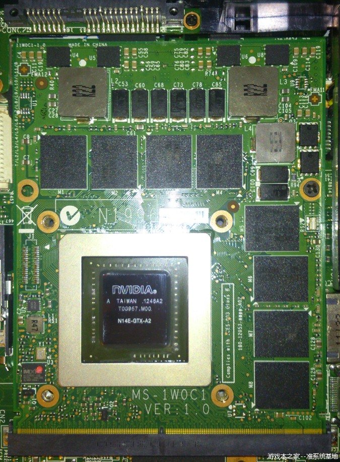
in general mxm cards between Dell (Alienware), Clevo, and MSI laptops are interchangeable, with some exceptions. ASUS is NOT included. They sometimes reverse the mxm connector pinout. Even when the pinout is not swapped they will use a different form factor. The MSI version of the 780m has been confirmed to work in your laptop (see here). Clevo cards and MSI cards are usually identical, or close to identical so I would expect the Clevo card to work as well. I do not know if the Dell version of the 780m will work in your laptop.1 point
-
The mobile equivalent to the PCI-e standard is called MXM, current revision is 3.1 (backwards compatible to 3.0). It's a standard that specifies a mechanical and a software interface for mobile GPU modules. Alienware adheres to those specs pretty well in many of their systems, e.g. AW17, AW18, M18x R1, R2, M17x R2, R3 and R4, M15x. MSI has shown decent MXM supports as well in the past. Clevo is a bit weird, while they praise themselves for full MXM compatibility (especially the reseller called eurocom), that's simply not the case. While the mechanical interface is MXM, the software mechanism is crippled in most systems and usually doesn't allow you to get a next-gen or even two gen newer card to work properly. That's really a pity, cause those systems could have great potential if the firmware was as well implemented as in for example AW systems. A reason to restrict MXM functionality is obvious... some OEMs don't want you to be able to upgrade the GPU for years, they want you to buy a new system. That's why Asus doesn't adhere to the MXM specs AT ALL. Different module size, layout, and especially software interface. No MXM compatibility there. Tl;dr: Mobile GPU equivalent to desktop PCIe GPUs is called MXM. With Alienware and MSI systems that use MXM you have a good chance that you can upgrade your GPU. With Asus you simply can't. With Clevo it's usually pretty tricky and newer gen cards than the system was shipped with most likely cause issues.1 point
-
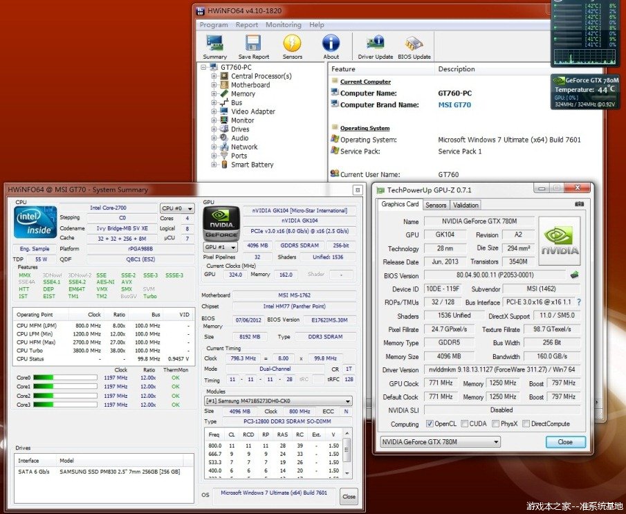
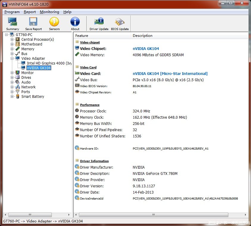
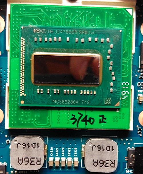
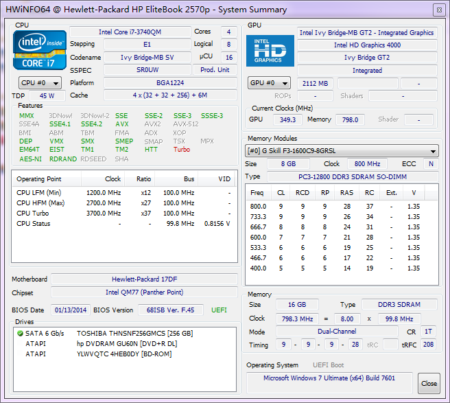
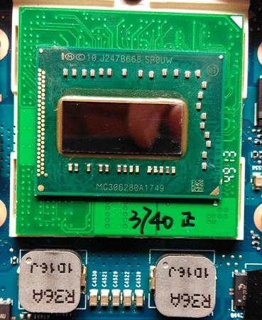
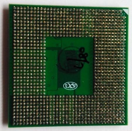
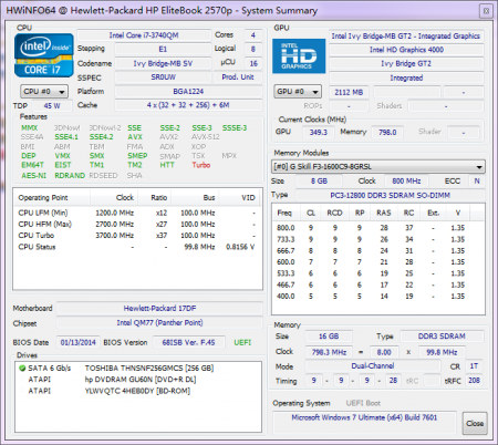
I replaced 3920xm QC22 es to 3740qm SR0UW BGA TO PGA and saved money. BGA TO PGA version cost about half price of original PGA version, just a little worry about the quality. The PGA pin is not so good at install to the socket. And it has two PCB boards, so is thicker than original PGA. I should pay attention to fixing heatsink screws slowly, prevent breaking the core. [ATTACH=CONFIG]12015[/ATTACH] [ATTACH=CONFIG]12016[/ATTACH] CPUZ detects it as PGA, but AIDA64 and hwinfo64 can detect it as BGA version. [ATTACH=CONFIG]12017[/ATTACH] also make a throttlestop test, cannot stand on x34, quickly get down to x33. x12 x23 x24 x25 x26 x27 x28 x29 x30 x31 x32 x33 0.8156 0.8956 0.9006 0.9156 0.9257 0.9457 0.9557 0.9757 0.9957 1.0157 1.0408 1.0658 10.8 19.3 20.5 21.7 23.0 24.5 26.4 28.2 30.2 32.6 34.7 37.1
 1 point
 -
I'll try to post the mod this week. 3.05 compared to v2.07 has quite some changes. Most importantly they locked it down, so flashing anything from 3.05 is not easily possible. Major BIOS changes include update ME firmware, new nvidia vbios, updated intel vbios, Win8.1 acpi entry and quite some "under the hood" fixes that most won't notice I guess.1 point
-
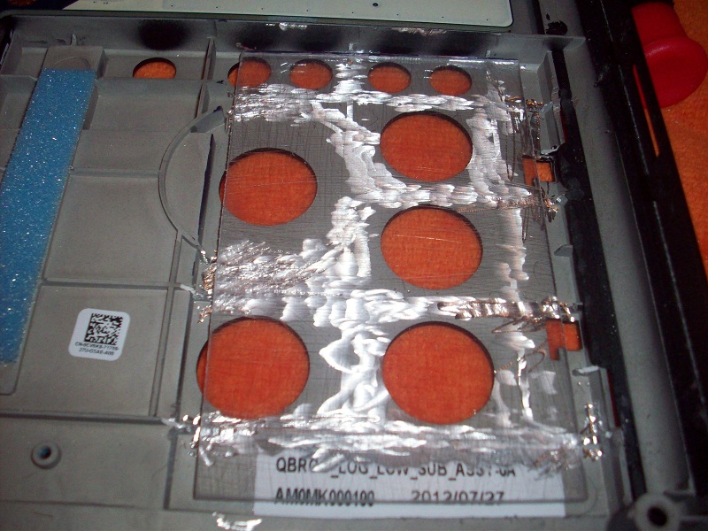
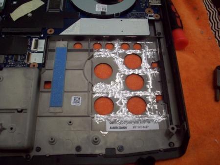
Pictures of the CPU heatsink. It wasn't as bad as the GPU heatsink. I didn't take temp readings before I did this so... yeah. CPU with the ID7. I don't like this stuff. It hardens over time and is hard to remove. I haven't been able to do it without scratching the die on my GPU/CPU. CPU heatsink after cleaning. The deformations in the heatsink from where the heatpipes were attached are clearly visible when reflected in the light. As I said above, this is not as bad as my GPU heatsink, which was really warped. It had high spots and low spots. Notice that the deformations run right through the center of the die contact area. Notice the insulating tape applied to the heatsink. This (I assume) is to prevent accidental contact with the row of tiny components on top of the CPU (see pictures above). I used a sharpie to blacken the heatsink. In theory, this would help me see the high spots and the low spots. Overall it was surprisingly flat with the exception of the where the heatpipes were attached. I removed a portion of the insulating tape. There isn't anything the heatsink base can contact on the short side. I also removed two of the mounting screws. Be care with the little plastic washers that retain the hold down springs. They are small. The washers are split in one spot. That is my machinist 1-2-3 block. One without holes would be a good choice since it would support the sandpaper better, but it's what I had so I used it. I used WD-40 to wet the sandpaper. I was pointed to a desktop CPU lapping guide and they used water and a drop of dishsoap. That would probably be better. Cleanup would be a lot easier. You just can't do this dry, it has to be wet. It is messy, so do it outside or someplace you don't want copper slurry. I used gloves too. One thing I should have done was remove the thermal pad along the lower edge of the heatsink. I ended up mangling the crap out of this without even trying. I pieced it back together. New thermal pad material has been ordered. I had 320, 500 and 1000 grit paper. I mostly used the 1000 grit since I didn't need (or want) to take off a lot of material. I got most of the deformation removed. I will come back to it later after my thermal pads arrive. Here is a picture of before I removed the ID7 paste from my GPU heatsink. The deformations from attaching the heatpipes can be clearly seen. I did find a pic of my bad repaste job. I noticed that my heat sink had some high spots in the middle, so I took a stone too it. These are the shiny spots in this picture. You can't see the bulk of the high spot because it's covered in thermal paste. It was much worse than my CPU heatsink.1 point
-
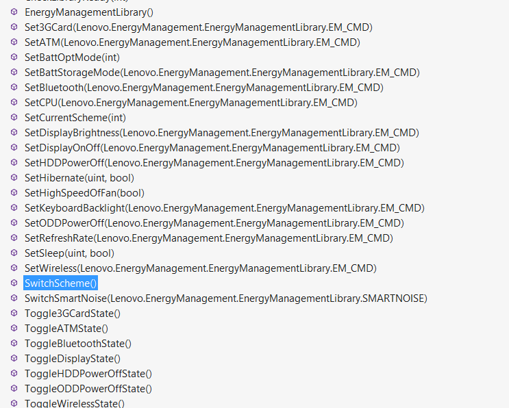
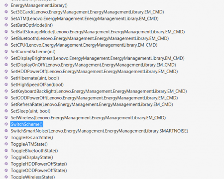
Not sure if anyone has found this, but i found some of lenovos api's for fan speed and things like keyboards under Program Files (x86) > Lenovo > Power Mangement > Lenovo.EnergyMangement.dll, LenovoEMExpandedAPI.dll, LenovoSDKEmSubSystem.dll I saw some people wondering about turning up fan speed and such, and there is a function called SetHighSpeedOfFan that sounds like a solution. There are also options for backlight, brightness, and a bunch of others. I opened it with VS Express, but i assume other programs would also work. Hopefully this helps some of you! Screenshot of some options:
 1 point
 -
Nope not really, the Clevo has double the ram so it may have better performance in games at higher resolution than 1080p vs the Dell card but that hasn't been tested yet. The Dell may do a bit better in synthetic tests like 3dmark 11 since it has half the memory and thus uses less power than the Clevo.1 point
-
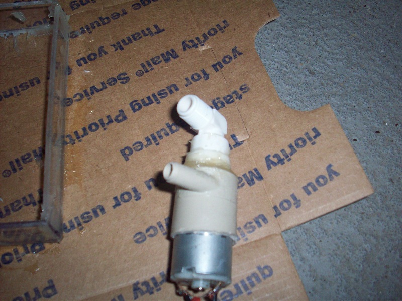
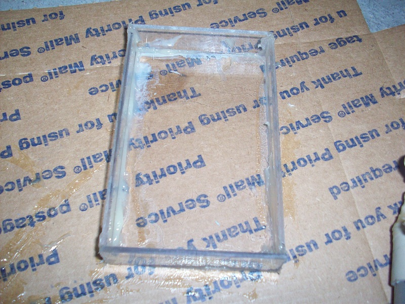
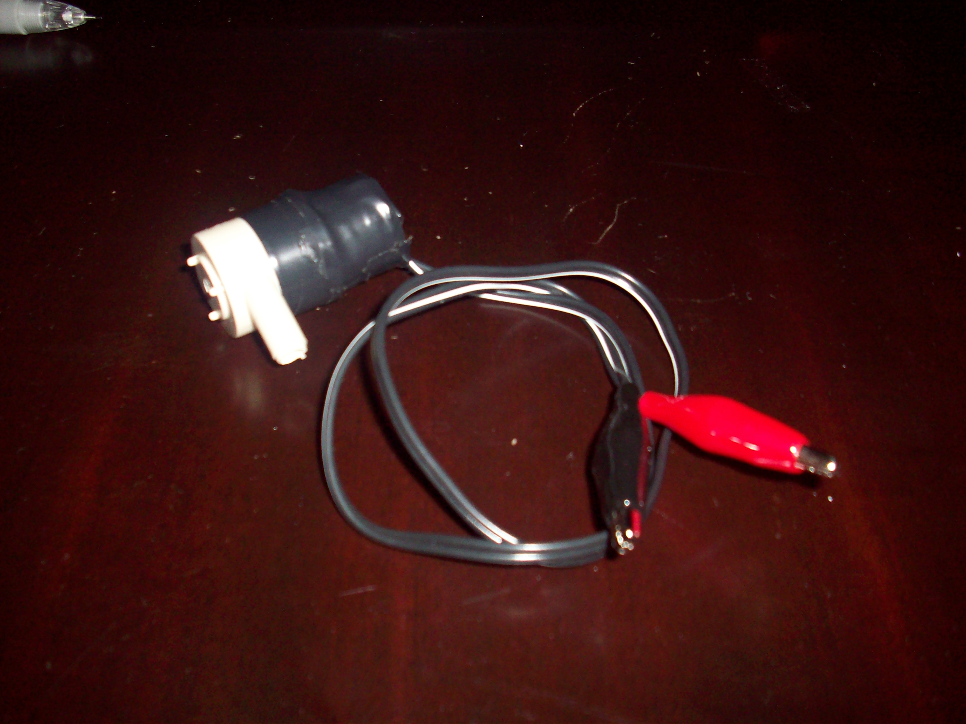
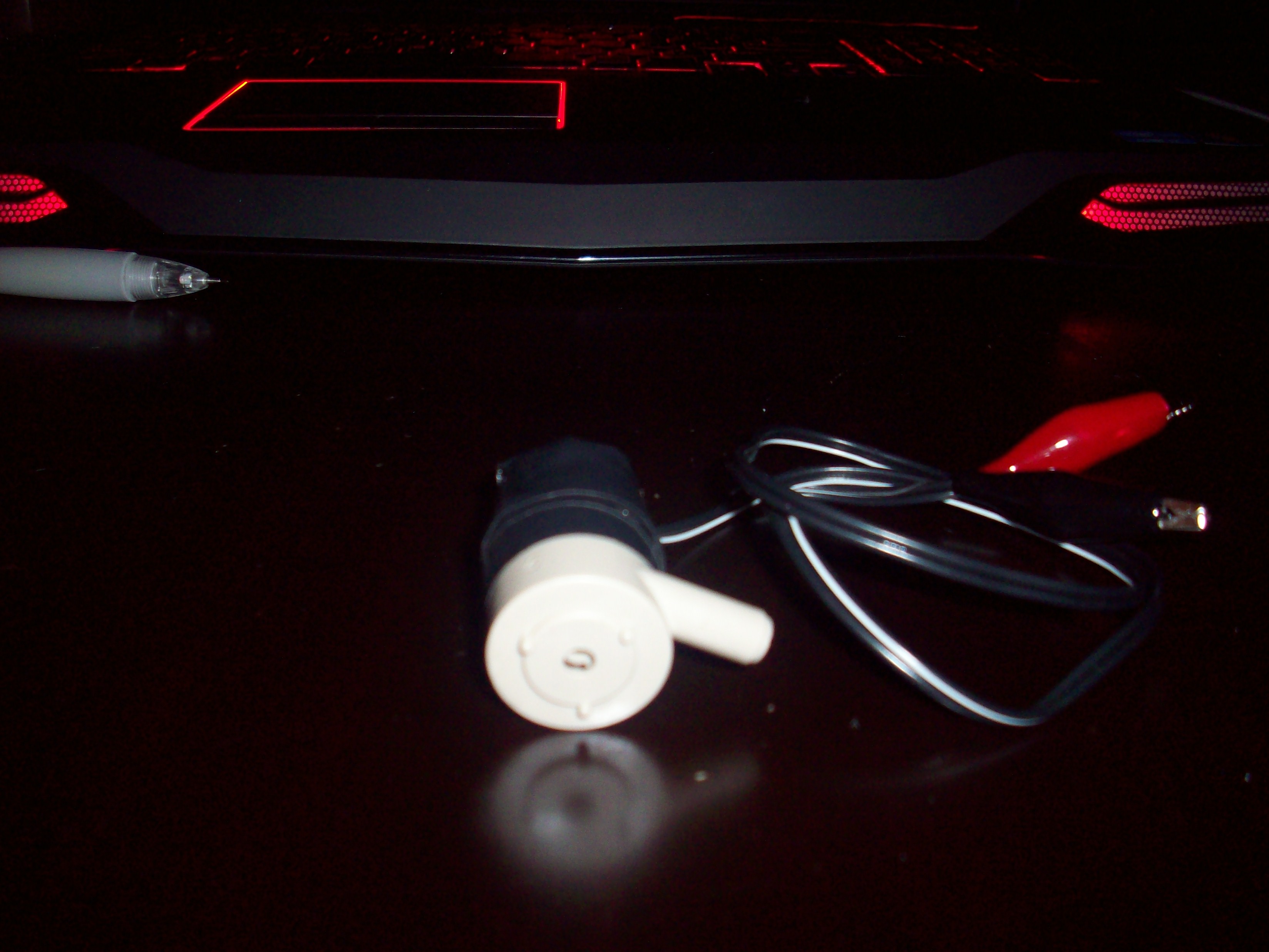
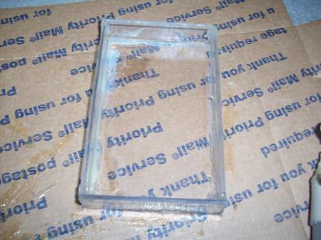
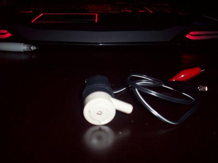
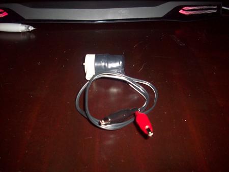
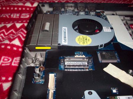
Update. Well I have been busy with finals and graduation, but I now free and have some progress. Here a submersible pump that I have converted into a non submersible. Also I have started the water reservoir. Alongside I have also shaved off some of the casing to give the reservoir clearance. I have also moved the power source connection now it will be extracted from the old speaker connection. Thoughts?


 1 point
 -
I have been trying to work on this mod as much as possible, but it is a bit difficult right now since I graduate in December and everything needs to be done by then. So far I have made my own water pump that will run from the CD drive power source. I have also bought my materials to make the acrylic reservoir and have started looking for fitting for the pipes. As for the matter of the piping flow rate I will have to look further into that issue since I haven't had much success receiving my spare heat sinks. I will be doing some extensive testing on the spare heat sinks and will report results.

 1 point
 -
Hi have a few questions after reading your reply. 1. In your diagram does the piping go through the heat sinks? (refer to the pictures attached) 2.Will water that runs faster absorb more heat? Or will the reservoir effect in the heat sink fins cool the water down more since it is hit with more air flow? As for your idea, it may be a little difficult to fit it the way you laid it out. That's why I went from one side of the motherboard to the other. On a side note do you think the movement of the current heat pipes and the grinding down of the heat sink to allow 2 other pipes to be in contact with the surface will increase heat removal?

 1 point
 -
@jackgarcia7 yea its a purple blue on my u2412m...get a better screen O.o EDIT:whoa...is my colors off or is this normal for a accurate screen. The Blue in paint says indigo and it looks blue/pruple. Unreal is that how it looks for you? yea no don't do that. Stalling is bad. You want flow because flow will extract more. errr i'll draw it out Alright here is my drawing. Hope this helps. I personally think it'll work better but that is if you can fit it in it. These 1/2 pipes are very large ^^ You could also do a 1/3" split into 2 1/4" pipes. See my area numbers below: 1/4 in 0.04908738521234052 1/3 0.08726646259971647 1/2 in 0.19634954084936207 2 1/3 =~1/2 and 2 1/4 =~1/3 Your biggest problem as i stated in the picture are surface area contact plus space to fit it. You may need to cut the case so the pipes lay inside and stick out of the case a little to give it a little more room. Read First!!!! And my drawing: http://img266.imageshack.us/img266/1783/personallymybetterdesig.jpg I hope i helped! Don't listen to me though do what you think works best! Good luck! I doubt you have enough space for my idea. EDIT: after though. I also don't know how well this will work. The only way i see this helping are these: 1. It increases overall surface area 2. it allows heat from CPU to be put onto GPU heatsink/fan (This is only big benefit in my eyes. Circulating heat does nothing unless it has an escape route and with no increased heat fin surface air and no increased air flow. I am not sure how much this will help. Granted the extra heat to heat fins and spreading heat between two heatsinks will help but I don't know how much it will.)* *An after thought to that statement. Someone else used the common idea of using ram heatsinks on the heat pipes and it made it worse. Reason for this was most likely the ram heatsinks ruined the flow of heat in the heat pipes and caused them to not function normally. So if you get any ideas or anyone else gets ideas on using ram heatsinks they are almost useless or detrimental if you don't drill bottom cause and use a laptop cooler since they screw with the heat pipes. He is the one cause i heard/saw ram heatsinks on the heat pipes caused issues. He was also the only one that didn't drill bottom case and not use a cooler. Something worth noting. BTW this was that NBR if i remember. If you can't tell i have put a lot of thought into this topic and it interests me a lot ^^ If your idea works i may follow whenever i get an XM chip when the prices drop in a year ^^1 point
-
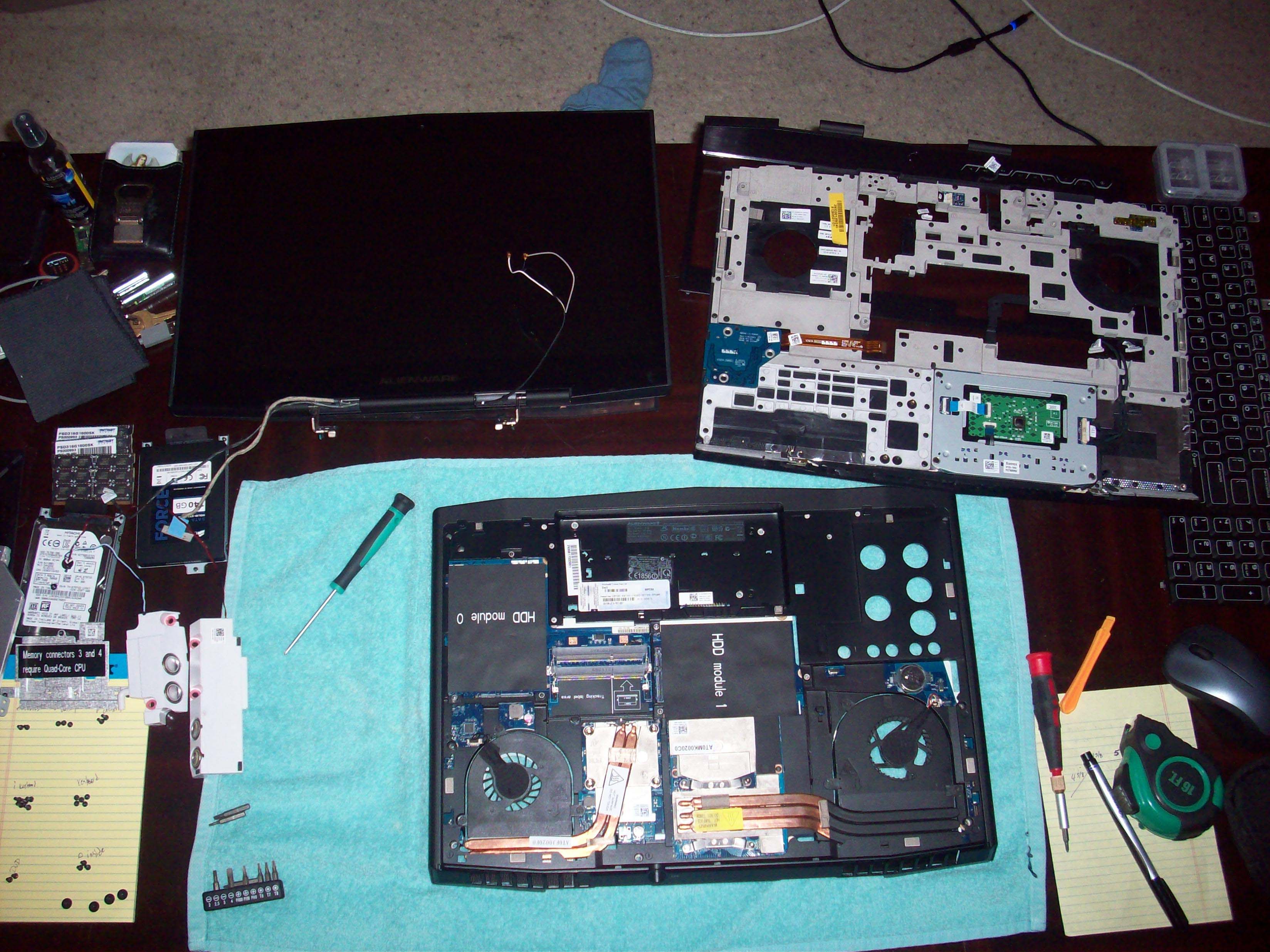
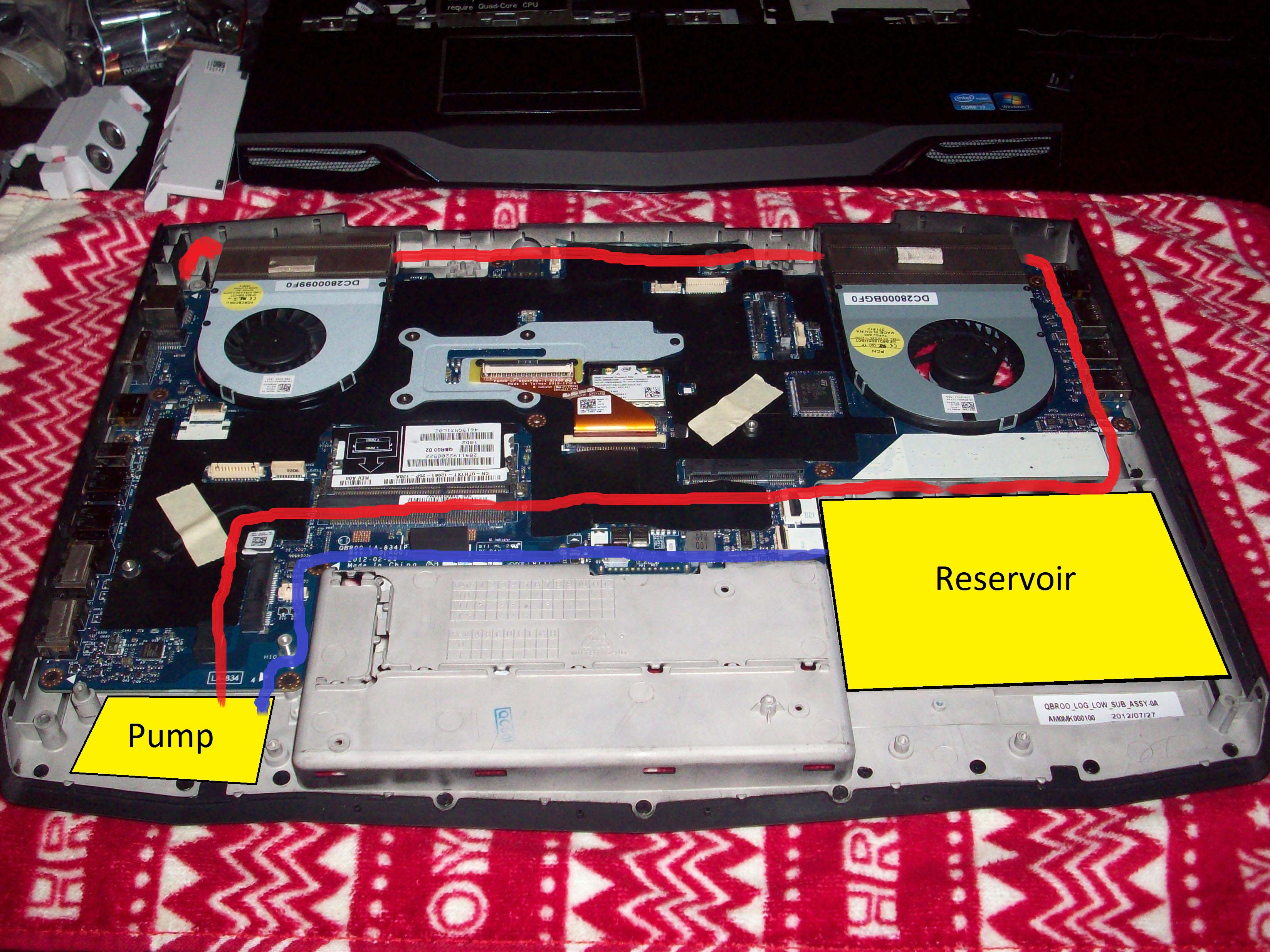
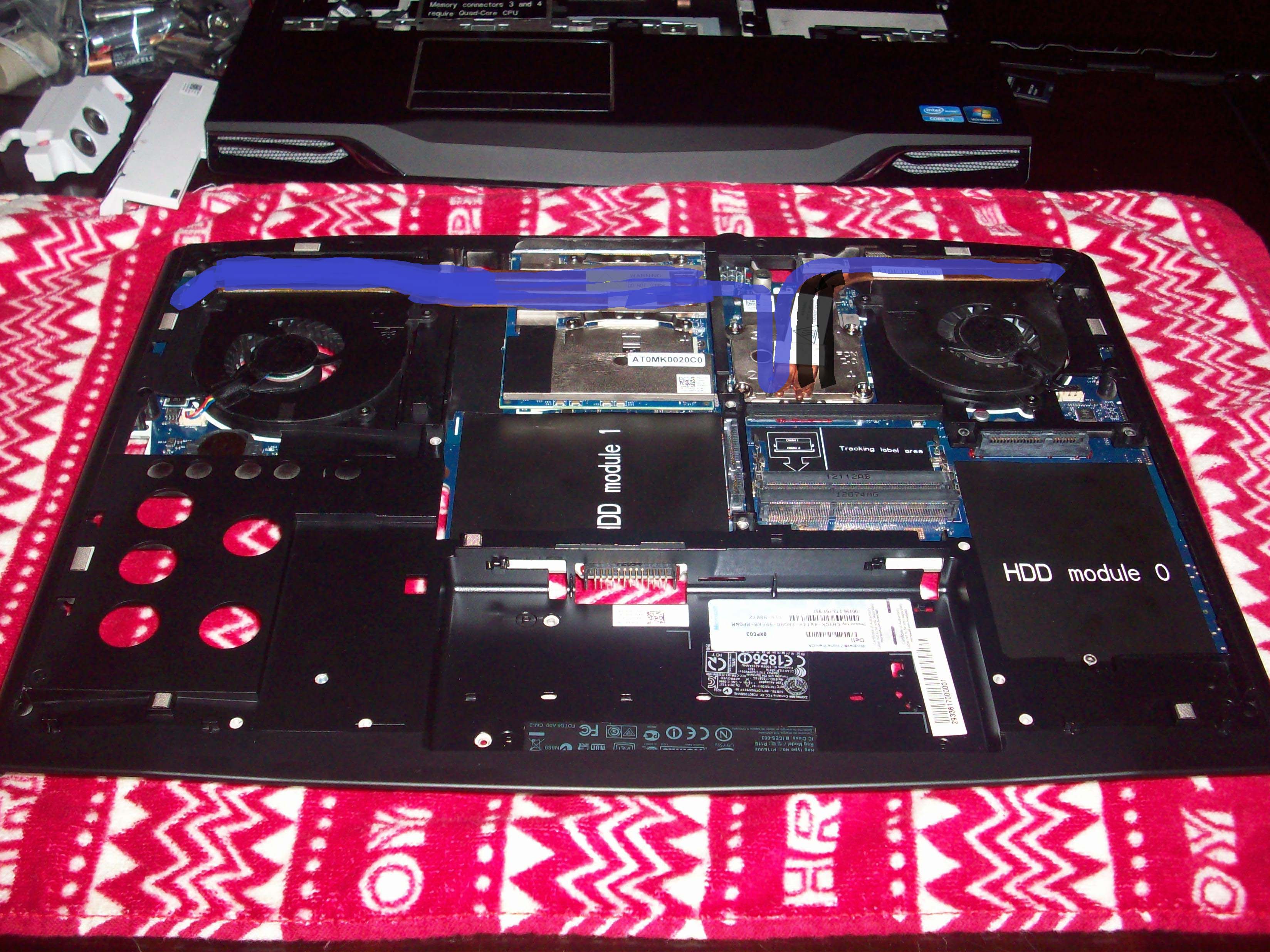
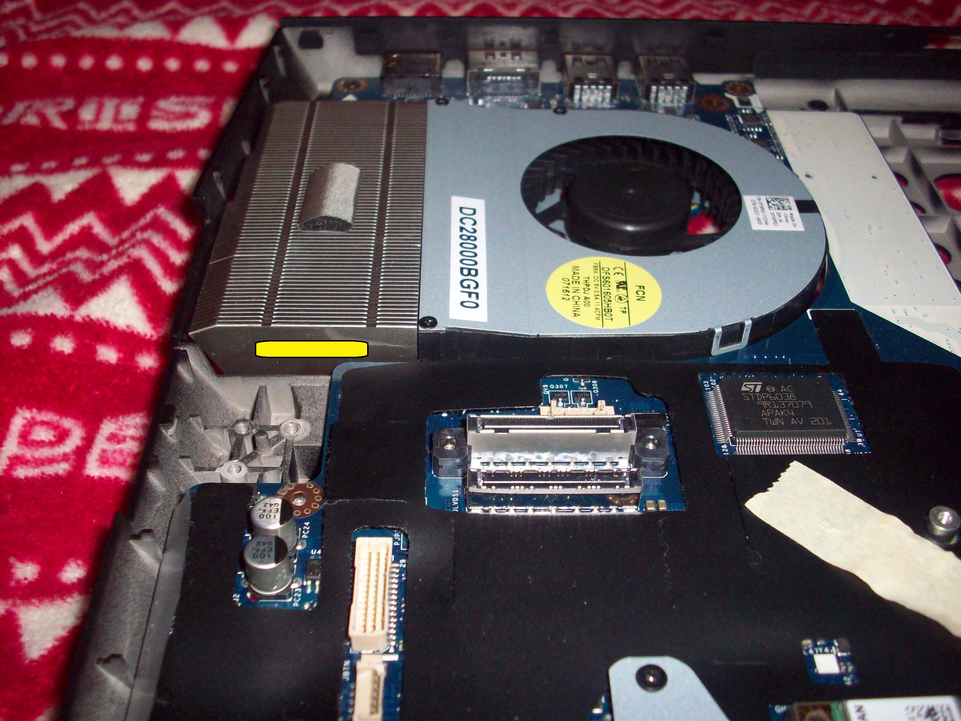
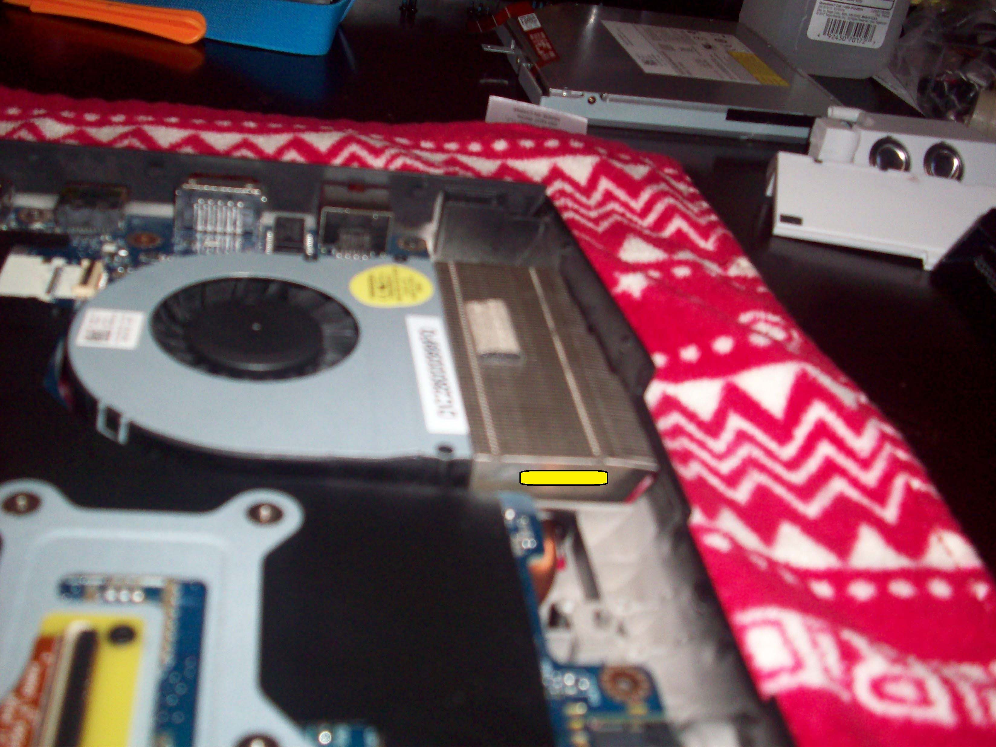
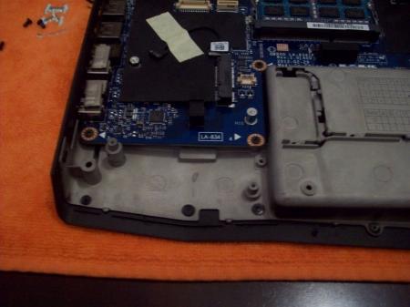
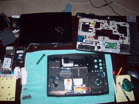
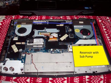
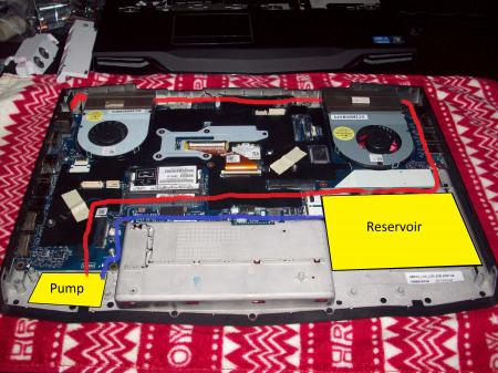
Well here is my schematic finally finished up. The first picture is only the tear down. After that you will see picture 2 and 3. When I receive the pump I purchased I will see what fitting is more appropriate. So far I am pushing for the one with the submersible pump. If it won't fit I will settle for the one I ordered, which is not submersible. Side note pump will be powered by CD drive. Both 2 and 3 show the layout for the copper piping on the front of the motherboard. Picture 4 shows the layout on the back of the motherboard. The layout is a little unique so I will explain it as good as I can. I will solder a 1/2 inch pipe to the 1/4 inch copper pipe which is what will be used overall. If you see the picture you will notice that all the piping will be layered over with extra flat piping. As for the CPU heat sink, I will take it to a machine shop to cut a score instead of slant that it currently has. That way I can move over the current heat sink and add the water copper next to them. Then I will do the same procedure to the GPU heat sink. Allowing all the heat sinks to be merge to spread heat equally. Finally to explain how the piping will cross through the heat sinks. I will drill through and solder a flatten 1/2 inch piece of copper piping through. This will give me 2 built in radiators. If you have any question or want to follow along with me let me know. I will give you a list of what I have gotten so far. Current I am just waiting for the extra GPU and CPU heat sink so that I put everything together. Will update soon and wish me luck.


 1 point