Leaderboard


Popular Content
Showing content with the highest reputation on 11/19/13 in all areas
-
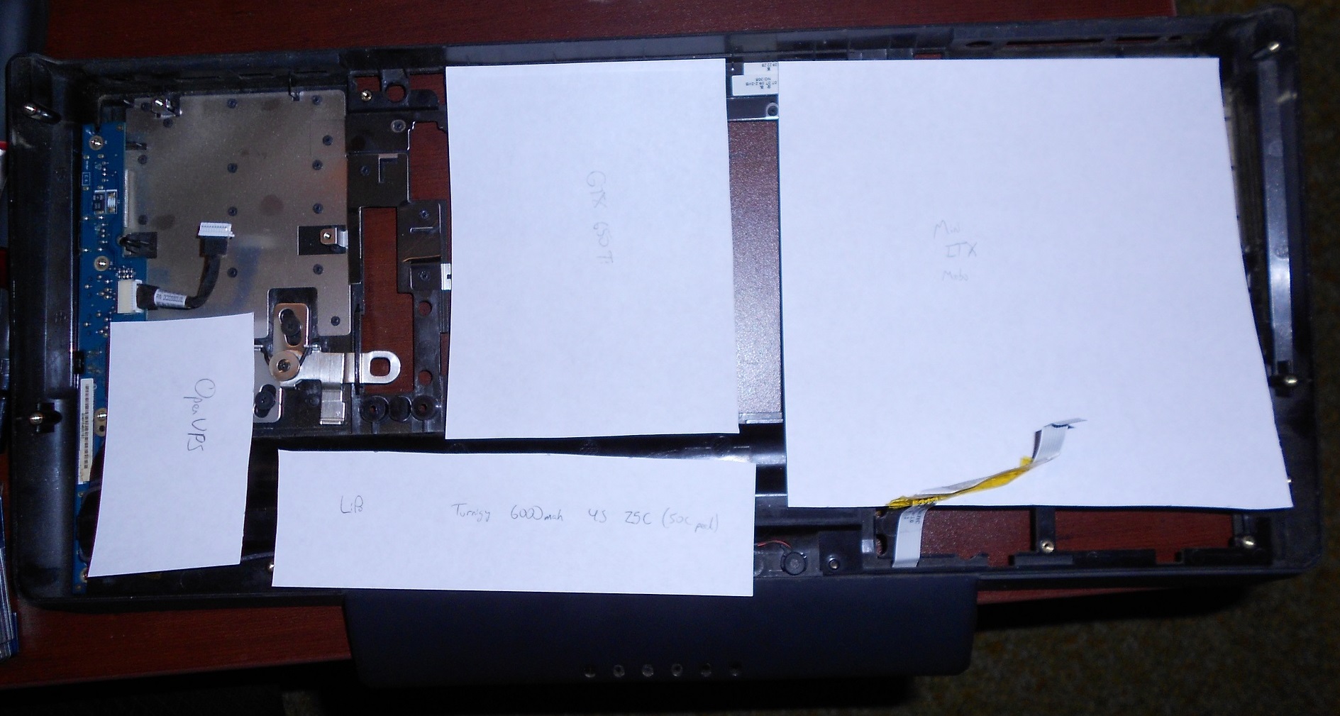
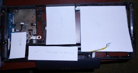
So I got a Dell M2010 that has a burnt up video card (like the rest of em) so I wanna re-purpose this behemoth using modern parts. I already have it gutted down to the bare inner chassis, so now I'm just taking measurement and trying to determine what could fit in here. I know that certainly I would like to use a desktop video card. And for battery life / wattage issues, the GTX 650 Ti seems to be the most reasonable: 110W (reference) and measuring in at 6" x 4.38" ( Newegg.com - Refurbished: EVGA SSC 02G-P4-3653-RX GeForce GTX 650 Ti 2GB 128-bit GDDR5 PCI Express 3.0 x16 HDCP Ready Video Card ). My current two largest issues: 1. Power. I can find lots of DC-DC converters and whatnot, but usually the output current is heavily lacking. OpenUPS This is almost perfect. Hook up a battery (more on this later), and pretty much any laptop charger (~19V or so) and it will output a preset stable voltage. It will swap between the battery only power or when a DC source is plugged in, it will both charge the battery and output the voltage (in this case 12V). LOOKING FOR SOMETHING BETTER (hopefully)! With the above, a LiPo battery would be superb (and it supports it!) Something like this: Turnigy nano-tech 6000mah 4S 25~50C Lipo Pack After my probably error ridden math, I got a result of 88.8 Wh. The stock Dell Li-ion battery is only 56 Wh! Downside to that OpenUPS, max output current is only 6A (can peak to 10A). So this is only 72W.... which is good for only the mobo+lower-end CPU (leaning going with a desktop motherboard for simplicity of the power issue). I'm trying to figure out how to get one with around a 200W output. This (200W) would be suitable for this project. picoPSU-160-XT, 160watt (200watt peak) , 12V input DC-DC ATX Power Supply This would probably work since it has 200W peak. But now I have the issue of a UPS circuit (for battery/DC load balancing) and someway to report battery levels. And battery charging too. LiPo will be the way to go for this project since space will get tight rather quickly. 2. Mainboard. I'm leaning toward a desktop mini ITX motherboard for this. Since these can come with Wifi + bluetooth, this is one less thing to worry about. MSI Z77IA-E53 LGA 1155 Intel Z77 HDMI SATA 6Gb/s USB 3.0 Mini ITX Intel Motherboard with UEFI BIOS - Newegg.com Like that (this board has a few issues however). This is where the issue of using a desktop board comes into play. Height. The PSU plug on the mobo linked about could not be in a worse location. It would be at the thinnest part of the "laptop" body, don't think I would be able to plug anything in. The body is under 28mm at this point! The rear of the case is a more manageable 38mm. Although, after measuring the 3 audio port stack on another computer, this was 45mm. Not sure what to do about that. This makes it rather tricky. A decent laptop motherboard would also work, I could setup the video card as an internal eGPU and that would work fine. Was thinking of something like the Sony SVZ chassis since they appear to have smaller motherboards yet support a pretty solid CPU and have a Gen2 link over mPCIe. Looking for laptop mobo suggestions (hopefully cheap laptops). --- Minor issues (relative): If desktop board, I'll need a PSU such as picoPSU-80 12V DC-DC ATX power supply this thing to power it, this is relatively really tall though and wouldn't work without modification. The form factor is superb though. I'll also need a PCIe x16 extender cable such as the below to allow the GTX 650 Ti to lay flat in the shell: PE-FLEX16-G2 PCI Express X16 Gen 2.0 Male to Female Extender Cable Orbit Micro KZ-B23 Series (x16/x8/x4/x1) Flexible x16 PCI Express Extender (not sure on PCIe 1.0 or PCIe 2.0 on this one) Driving the screen. As mentioned in the large DIY eGPU thread by matrix666, something like this would probably work (and allow me to use video input on this large screen): M NT68676 2A HDMI DVI VGA Audio LCD LED Screen Controller Board DIY Monitor Kit | eBay Keyboard. The M2010 keyboard is quite nice. I tested it with my other laptop, picked it up right away (KB is bluetooth), all works fine, no issues. However, I have not a single clue how I would charge this thing. I cannot figure out the pinouts at all for this dock connector thing. It probably has a SMBus Clock and Data pin, also a System Detect Pin to see if the keyboard is attached. Not really sure how to go about this (read: Help me here please.) Bottom of the list: Then I gotta wire this all up and hopefully integrate it nicely with some of the Dell stuffs (like the powered screen latches, the power buttons, DVD drive mechanism). Price: What I have: Laptop: free! M2010 Mobo: -70$ (will try to sell for about 70$) What is on the 'pretty much certain list' : GTX 650 Ti: ~125$ (or whatever might be on sale) OpenUPS: 120$ Turnigy nano-tech 6000mah 4S 25C LiPo battery: 65$ The Perhaps-Maybe-Potential list : Desktop mini ITX mobo: 100-125$ CPU: 125$ (or more depending) RAM: free (got some) Total: -70 + 125 + 120 + 65 + 125 + 125 = 490$ Holy asterisks. That turned out a lot more expensive than I would've expected ..... Accepting donations ;-; ------ Please make any suggestions, comments, 'you missed this' , 'you are crazy' , etc. (Hopefully that is readable, I wrote this as I was searching around) -atn --- Questions I need answers to before continuing with this mod: 1. Laptop or desktop motherboard? If so, which? Laptop must be 2nd-gen i-Series (6-series) or later. Desktop is a bit more flexible. I would like to have 3rd/4th gen i-Series if possible. 2. Suitable battery charger / power output. The OpenUPS is great if it wasn't 72W. Something similar would be superb. - Everything will fall into place after these decisions are made. Then will just have to incorporate it into this case and wire it up so it looks stock. Need to figure out keyboard charging (hopefully with the help of triturbo this will happen soon-ish). Welcoming more wiring schematics for the M2010. Latch assembly mainly. triturbo posted the one for the buttons/lights/ODD. Will have to figure out how the ODD mechanism works, but not worried about that for now. --- Picture~
 2 points
 -
I followed the youtube video Lenovo Y400 Y500 Full Disassembly - YouTube. However, the video was probably created with a prototype y500 because some of the layout of the laptop did not match mine. Most noticeably is that there are *three* screws holding the keyboard down not *two*, I almost ripped the keyboard trying to pull it off with one screw still in there. Also, a few of the ribbons are located in different places which I think is an improvement over the y500 in the video. Finally, the hardest part of the entire process was to remove the back cover because it is held on by plastic tabs facing in different directions so the best way is to wiggle it left and right while lifting and not lift directly up. That is just regular white thermal paste on the heatsinks. The OEM thermal paste resembled AS5 in color and thickness and I recommend that it be left alone if the temperatures are good. I have since replaced the cheap stuff I put on there with AS5 and still have not seen the temperatures I saw when it was stock (still 3-5C higher). Here is what I did to stop the twitchy touchpad (issue is well documented in the Lenovo support forum) and the random extra characters the keyboard would add while typing (less known issue).1 point
-
Optimization Guide for Battlefield 3: For Nvidia Users: Threaded Optimization + MaxPrerenderedFrames: Open Nvidia Control Panel --> Manage 3D Settings --> Program Settings --> Battlefield 3 Set Maximum Pre-rendered Frames to 1. (effect: system prerenders only 1 frame instead of 3, results in less game stuttering) Set Threaded Optimization On. (effect: loading times reduced) FXAA Enable: If you're using NVIDIA Geforce Driver 290.36 Beta or higher, you're able to use FXAA. NVIDIA Inspector is the best choice to activate FXAA. Download NVIDIA Inspector 1.9.6.4: [ATTACH]4105[/ATTACH] Open NVIDIA Inspector and click on the tool-button. Choose Profiles --> Battlefield 3 and under Antialiasing set NVIDIA Predefined FXAA Usage to Allowed and Toggle FXAA on or off to Enabled Danoc1 FXAA Injector: This is an adjusted FXAA Injector for BF3. (source: PCGH Forum) Copy all files to your Battlefield 3 installdirectory. Delete older version before copying the new one. Difference between normal and performance version is, that the performance version has disabled Ambient Occlusion. Attention: If you copy your commands in your own user.cfg file over to Danoc1's file, the user.cfg file has double commands like RenderDevice.ForceRenderAheadLimit and RenderDevice.TripleBufferingEnable New version 1.3 Beta released: (Changelog see Post#17) Directlinks: Danoc1 FXAA v1.3 Beta Danoc1 FXAA v1.3 Beta performance older version 1.25: (Changelog see Post#10) Directlinks: Danoc1 FXAA v1.25 Danoc1 FXAA v.1.25 performance FpsLimiter: NVIDIA Inspector 1.9.5.11 has a Frame Rate Limiter function implemented. NVIDIA Geforce Driver 280.26 WHQL or higher is required. It's your choice to set a global FPS limit or for a specific game. For all users: user.cfg: This file copied to your BF3 installdirectory (C:\Program Files (x86)\Origin Games\Battlefield 3) activates console commands at BF3 startup. Write all tweak or information console commands in the user.cfg file, which you want to have enabled every time you play. Download user.cfg: user_cfg.zip FXAA: Console command: WorldRender.FxaaEnable 1 Danoc1's FXAA Injector is recommended, link above. Performance improvements: Console commands: RenderDevice.TripleBufferingEnable 0 (effect: performance improvements) RenderDevice.ForceRenderAheadLimit 1 (effect: system prerenders only 1 frame instead of 3, results in less game stuttering) Mouse sensitivity: Disable Origin IngameOverlay Origin --> Settings --> In Game --> uncheck "Enable Origin In Game"(effect: better mouse feeling, it's no more spongy) Max FramesPerSecond: Console command: gametime.maxvariablefps X (X stands for the MaxFPS you want, e.g. 60). Ingame Performance Monitoring: Console commands: render.drawfps 1 (effect: current FPS displayed, upper right edge) render.drawscreeninfo 1 (effect: information on the display used, upper left edge) render.perfoverlayvisible 1 (effect: CPU and GPU usage displayed, down left edge) TweakGuides: Battlefield 3 Tweaks and Fixes Geforce.com BF3 TweakGuide Now, that you're prepared...See you on the battlefield.1 point
-
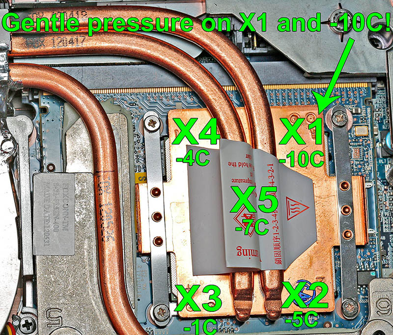
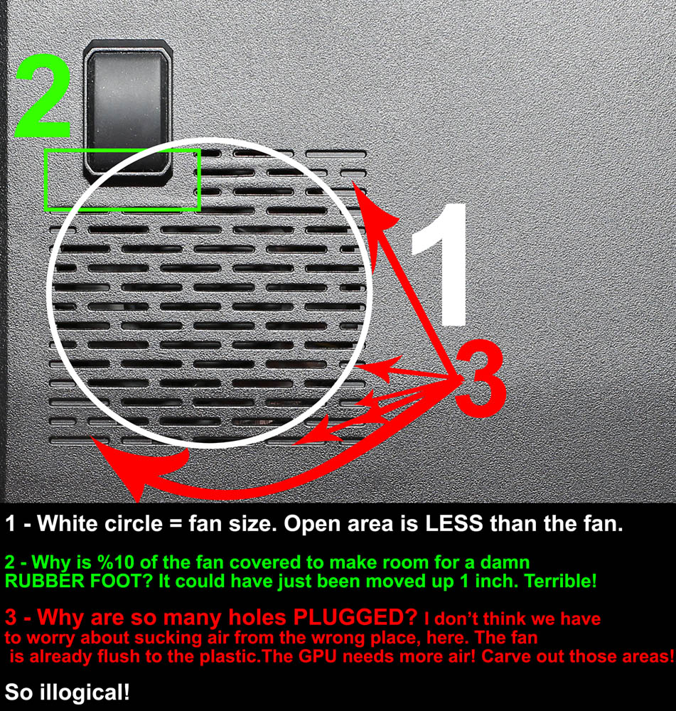
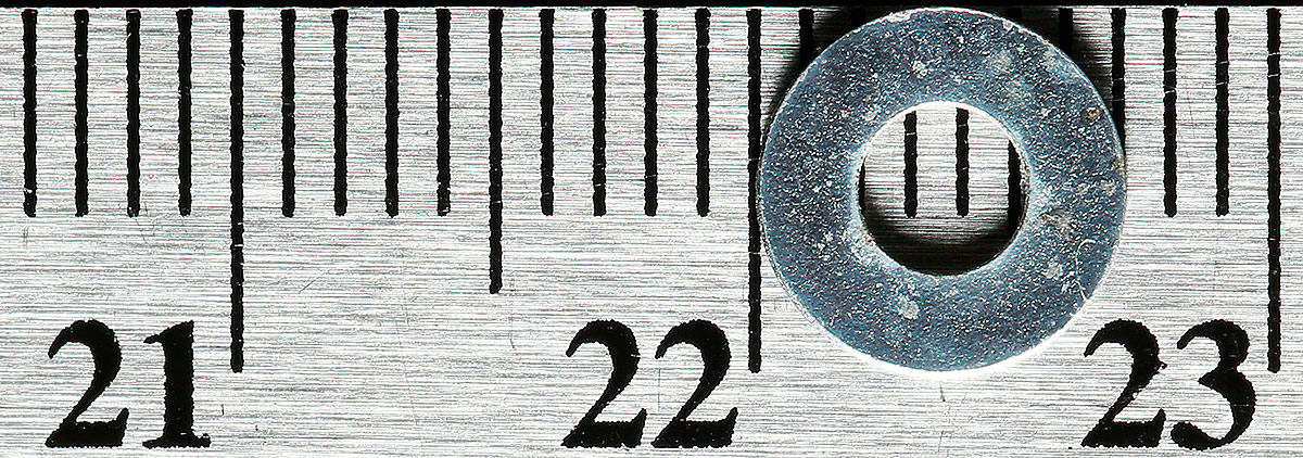
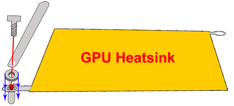
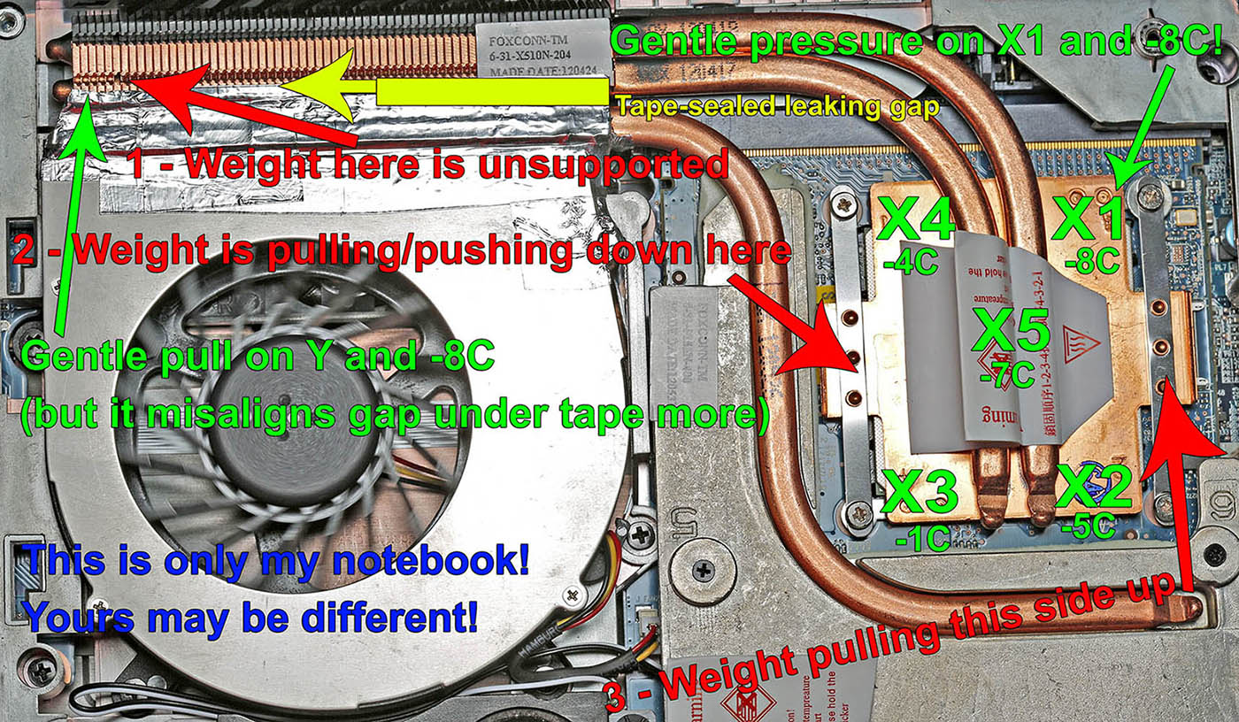
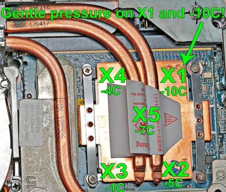
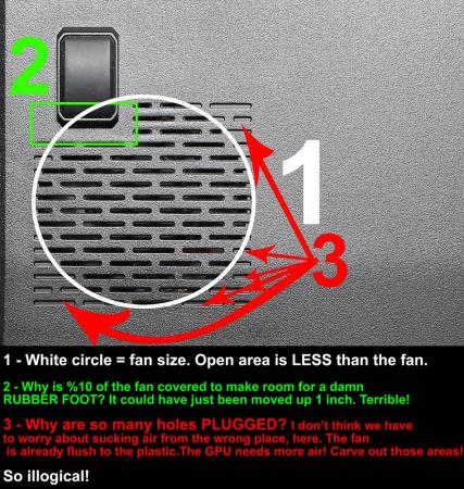
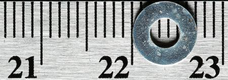
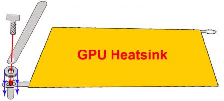
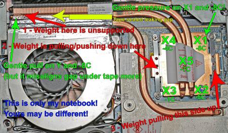
Edit: %100 fan function is now available in custom BIOS for any P150/P170 (and many other Clevo models) thanks to Prema's BIOS mod! http://forum.techinferno.com/clevo-sager/3119-premas-mod-bios-latest-stock-bios.html For all those with Clevo 150s and 170s that have heat issues, Clevo has somewhat neglected their customers by calling them high performance gaming notebooks, then completely slacking on their cooling system installations and designs. These issues are all discussed on many separate threads, but I've consolidated them here for ease of research since it took me quite awhile to piece this all together for my own solutions. With no exaggeration, models affected by poorly installed systems result in unnecessary 15-30C gains on various P150 and P170 models. It is a lottery of which machine gets bad installations. For me it was poorly installed on the 7970M GPU I ordered with it. I've been told this has can be a problem with the CPU as well from other owners, but in my case, the CPU cooling system was well installed and wouldn't benefit from any pipe modification. I am using a P150EM + AMD 7970M, and guess what? But, who am I to complain without offering solutions? I'll list the issues then address or link to each one. If this guide ends up helping you please +rep thanks Index of issues: 1 - The CPU and/or GPU heatsink can be improperly pressured. This results from improperly installed pipes that add leverage to the block, or the block itself doesn't have enough pressure on it because the metal mount tabs are too flexible; EVEN WITH SCREWS %100 TIGHTENED. Solutions below! 2 - Poor alignment between pipes and/or fins to the fan which leaves air gaps. Tape can be used to fix this. Solved in this thread: Seal air leaks with tape 3 - The plastic shell cover on the bottom of the notebook restricts airflow throughput by an unacceptable margin of at least %50. The vent ports are horribly designed and has been compared to "breathing through a sock" I get -12c instantly after taking mine off. 4 - Custom Fan Policies . As of late, there are now custom BIOS that allow %100 fan mode for any P150EM. Good for those hot days where you really do need maximum cooling. First, a big diagram of all the inner problems: (the red text 1,2,3 is step 1,2,3 for issue #1) I must mention the testing of uneven pressure is with this notebook is upside down. The adjustments you make may shift around when you flip the notebook back over, but, it still should be improved if you had alignment issues to behind with. While you will be using the notebook right side up, it is much easier to test for the pressure problems upside down. The final washer/support fix should be done right side up, and with much more patience than upside down since it takes more coordination to do it right side up. I got underneath it like you would a car and had it sitting on an opened elevated platform while I tightened screws and read the heat measurements. TESTING IF YOU NEED SOLUTIONS TO ISSUE 1: Before you try either, you must test and find out where the pressure needs to be applied first. Temperature reduction is instantly noticeable doing this test. The easiest way to figure out if the GPU heatsink is loose even after the screws are all the way in, and to avoid airflow restriction while running, is by having the notebook upside down with lid closed, back plastic cover off, and connected to an external monitor while running Kombustor. I first let Kombustor run at 1920x1080 for 4-5 minutes to let the heat levels to stabilize. Then, as it was running I pressed on the GPU block very gently with pencil eraser at different points while monitoring the temperature changes with each press. I got up to -8C drops immediately, so this let me know that my GPU was not flush with the heatsink. Doing this upside down first allows you to take your time slowly and methodically. I personally find it best to take it easy first so you can draw an accurate conclusion. Then when you know its not like it should be, do it right side up. When its right side up it will need a better prop of the notebook in order to allow you to press on the GPU and avoid blocking the fan intake, so make sure you prop the notebook firmly first. I'd advise not to use a metal object to do any of this poking around. Use something like the plastic head of a screwdriver or a pencil eraser to apply pressure to the heat blocks. The first big photo was -8C while running hot for the first time on a fresh application of IC Diamond compound. The compound cured a bit after several runs of Kombustor, and I was able to sustain -10C as shown in the next photo. SOLUTIONS IF THE TEST REDUCED TEMPS: Solution 1A - The metal strip mounts dont apply enough pressure because the screw shaft sockets limit how far the screws can go down. Design flaw (erhm, Clevo oversight) In addition to these shaft sockets which limit how deep the screws can go, there are 2 additional ring tabs underneath the main metal tabs, sticking out of opposite corners of the GPU heatstink. They are hard to notice at first, but these can be used to add pressure with the existing screws. They go around the socket shafts instead of resting on them like the main tabs do, so you can use washers as spacers to push down on them and add more pressure! Use washers small enough to avoid touching any outside circuits, but large enough in the center to slide over the shaft. Acting the same as if I leveraged the pipe assembly in solution 1A, I got -8C after putting in two 1mm thick washers and screwing them down. If you are going to install washers under certain screws, fully tighten the screws that you are not going to use washers on, first, but Don't tighten the screw with the washer underneath it as hard as you can. Take small incremented steps tightening the screw with the washer underneath it and check your temps each time you tighten. Once the temp stops dropping and teeters between 1 or 2 degrees, then you don't need to tighten anymore. EDIT: Was asked for washer size. I didn't buy anything since I have a drawer full of random tiny washers, but I measured it: 3mm inner, 7mm outer, and like 8/10 a MM thick: Solution 1B The heat pipe assembly has nothing firmly supporting it at the opposite end of the GPU where the copper fins are. This uneven weight acts like a lever on the heatstink, pulling or pushing it away from the GPU die surface. To find out if this is a problem for you, once your GPU is cooking at normal max temp, put gentle pressure on the copper fins. If the pressure reduces temps from normal, you have the weight of the pipe assembly leveraging your GPU heatstink and something needs to be stuffed somewhere to support it. Also do this procedure in the opposite direction to check both ways. I got an instant -6C to -8C change when I pushed the fin end up properly, and instant +8C when let go. Supporting the pipes will cool your GPU without even making anything tighter. You may only need a sliver of something to push on it, or way more. It depends how bad your copy is bent out of alignment. Reference the big diagram above for this solution. Solution 1A was better for me since solution 1B enhanced the air leak gap problem that the tape fixes in issue #2. Yours might be bent differently and actually improve the gap and GPU pressure if you're lucky. YMMV! Solution 2: Tape! Shown above and first fixed here: Seal air leaks with tape Issue 3: Solution? A newly designed fan port. This one really ticks me off unlike any of the other issues. I can understand the other ones, but this one is just from an epic failure in thinking it out: A cover that blocks airflow more than it allows. This is by far the biggest issue for all %100 of our notebooks. Mine personally runs at 94C with the cover, and 80C without. Clevo should know that cooling doesn't work by restricting the air feed, which is exactly what they did here with their design to a surprising extent. I mean really, you can just look at other notebooks and you'll see much better port designs that makes the fan the only major limiting factor in CFM capacity. I'd really love to cut out the plastic port grate entirely and maybe add some type of thin aluminum plate with a more flow-friendly design. And why the hell is %10 of the fans airflow space blocked for a rubber foot? This just tipped it over into the realm of stupidity. You can move the foot 1/2 an inch over and give the fan %10 more airflow, can'tcha? I'd love if there were a redesigned cover for sale but I doubt that'll ever happen. Time to bust out the Dremel. And the epic fail: Issue 4: This issue really blows. We need custom fan policies! Please give us a program with the ability to create and manage our own fan policies as well as some default profiles with options on how aggressive you want the cooling to be. Also, FN+Key for %100 fan would be a great addition as well: Edit: %100 fan function is now available in custom BIOS for any P150/P170, thanks to Premas BIOS mod! http://forum.techinferno.com/clevo-sager/3119-premas-mod-bios-latest-stock-bios.html So to sum it up, with the bottom plastic cover on I was maxing at 97C before addressing any issues and 94C after taping the leaks and fixing the GPU pressure. With the lid off, I run 80C even 26 minutes into Kombustor. Yep, plastic cover, you suck! I also suspect I can gain -2c to -4c with a more generous application of IC Diamond since the application I paid for still wasn't enough to fill the gap with all the screws to maximum tightness.
 1 point
 -
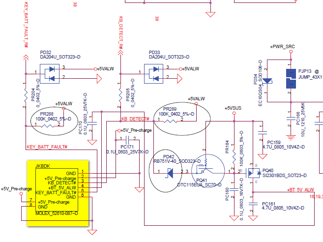
Here it is. You pretty much guessed them
 1 point
 -
Awesome machine and pretty awesome mod you got there! Is this of any help? If the connector is 30 pin, it should be1 point
-
Which is 10C lower than Intel's maximum temperature rating of 105C so you're operating within the manufacturer's specifications.1 point
-
Will you mod new vbios windows 8.1 for Y500 GT650m sli ?1 point
-
@Diarek One Question, have you the Setup 1.x? @All I've now my second eGPU, I've also done some testing with my Lenvono x220 and different GPU, would anyone have a problem when I would represent the tables here? Also I have made some test on the PE4L-EC060A and em-PE4L EC100A, plus I would have a few tables. Or is it not necessary? The image of my new Case you get, but in any case : If you still have any questions, ask. PS: I love the number of smilies here1 point
-
For the fan intakes I fit a small file into the existing slits and doubled them in size. The airflow improved so much that the GPU temps do not improve at all if I remove the bottom cover. CPU temps improve 1-2C still. By far the biggest improvement was sanding the heatsink plates. The reason why increasing pressure helps is because the plates are bent during the process clevo uses to bond the heatpipes to the plates, and very high pressure bends the plates, flattening them against the die. You can see the stress marks in the heatsink plates under the heatpipes where the processors contact the heatsink plate. This got me around 15C on CPU and 10C on GPU over what pressure increase mods got me.This mod also renders pressure mods pointless since the plate no longer needs to be bent into shape. It's such a shame clevo does this bonehead crap since the components used for cooling really are heavy duty and should. End users should not have to correct these mistakes.1 point
-
An x1 2.0 link provides 500MB/s (or 5GT/s) of bandwidth. Thunderbolt 1 is equivalent to an x2 2.0 link which provides 1GB/s (or 10GT/s). While Thunderbolt does provide additional bandwidth, you cannot run Optimus compression with it as Optimus requires an x1 link. The compression provided seems to exceed the performance of having an x2 link based on the benchmarks out there, even with people who have tried using Expresscard and mPCIe slots for their eGPUs. Thunderbolt 2 however is likely going to win the bandwidth war as it is essentially an x4 2.0 link, providing ~20GT/s in bandwidth. At this level of bandwidth most video cards are able to achieve roughly 80-95% of their performance based on the scaling analysis that has been performed (again links to this are present on the front page of the thread). The trouble with Thunderbolt right now is that all of the TB external PCIe solutions are horribly expensive ($300 and up) and it's not widely adopted on laptops, leaving your choices of laptops fairly limited. For me, I want a convertible laptop that will be replacing an aging desktop PC I have, and I have my eyes on the Sony Flip 13. It doesn't have Expresscard, Thunderbolt or mPCIe slots, but it has 2 of the NGFF M.2 connections inside. One of them could provide the same bandwidth (or more even!) than Thunderbolt 2 as it is an x4 slot and the M.2 standard is meant to support a 3.0 link, meaning a total bandwidth of ~32GT/s would be available if a 3.0 link is negotiable. I'm reluctant though as the laptop is going to be $1600 and NGFF M.2 slots are so new, no one has done any testing with them (I may have to be first!).1 point